Difference between revisions of "HVDigitalPot2"
Jump to navigation
Jump to search
Blwikiadmin (talk | contribs) (Created page with "File:HVDigitalPot2-crop-512pxV.jpg == Features ==") |
Blwikiadmin (talk | contribs) |
||
| Line 1: | Line 1: | ||
[[File:HVDigitalPot2-crop-512pxV.jpg]] | [[File:HVDigitalPot2-crop-512pxV.jpg]] | ||
| + | |||
| + | == High Voltage Digital Pot (10-bit) == | ||
| + | |||
| + | [[File:Fronthvpot.png]] | ||
| + | [[File:Backhvpot2.png]] | ||
== Features == | == Features == | ||
| + | |||
| + | Most digital potentiometers are limited in the voltages that they can have at the end terminals to be within +5V and Ground. This makes operation with high voltages difficult. This design allows for higher voltages on the end terminals. | ||
| + | |||
| + | * Single-channel, 256-/1024-position resolution | ||
| + | * 20 kΩ, 50 kΩ, and 100 kΩ nominal resistance | ||
| + | * Maximum ±1% nominal resistor tolerance error (resistor performance mode) | ||
| + | * 20-times programmable wiper memory | ||
| + | * Rheostat mode temperature coefficient: 35 ppm/°C | ||
| + | * Voltage divider temperature coefficient: 5 ppm/°C | ||
| + | * +9 V to +33 V single-supply operation | ||
| + | * +9 V to -16.5 V dual-supply operation | ||
| + | * See data sheet for additional features | ||
| + | |||
| + | == D/A Converter == | ||
| + | |||
| + | ICs are Analog Devices part number AD5292 PDF Datasheet. | ||
| + | |||
| + | == Connectors == | ||
| + | |||
| + | === J1 - 8 pin Header === | ||
| + | |||
| + | # +12V | ||
| + | # GND | ||
| + | # +5V | ||
| + | # Din1 | ||
| + | # Din2 | ||
| + | # CLK | ||
| + | # CSN | ||
| + | # GND | ||
| + | |||
| + | === J2/J3 - 3 pin Header === | ||
| + | |||
| + | # A side | ||
| + | # Wiper | ||
| + | # B side | ||
| + | |||
| + | == Driver == | ||
| + | |||
| + | Here is the 10-bit High Voltage Arduino Driver. | ||
| + | |||
| + | === Accelerating Writes === | ||
| + | |||
| + | Here are some notes on accelerating writes by using the SPI bus pins on the Arduino. Note that this card has a single chip select line and separate data lines which does not allow SPI transfers to be done. To do SPI there would need to be separate chip selects and a common data line. | ||
Latest revision as of 12:54, 10 January 2020
Contents
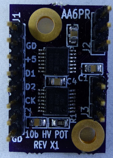
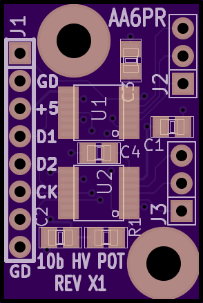
High Voltage Digital Pot (10-bit)
Features
Most digital potentiometers are limited in the voltages that they can have at the end terminals to be within +5V and Ground. This makes operation with high voltages difficult. This design allows for higher voltages on the end terminals.
- Single-channel, 256-/1024-position resolution
- 20 kΩ, 50 kΩ, and 100 kΩ nominal resistance
- Maximum ±1% nominal resistor tolerance error (resistor performance mode)
- 20-times programmable wiper memory
- Rheostat mode temperature coefficient: 35 ppm/°C
- Voltage divider temperature coefficient: 5 ppm/°C
- +9 V to +33 V single-supply operation
- +9 V to -16.5 V dual-supply operation
- See data sheet for additional features
D/A Converter
ICs are Analog Devices part number AD5292 PDF Datasheet.
Connectors
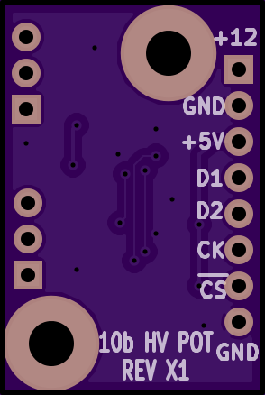
J1 - 8 pin Header
- +12V
- GND
- +5V
- Din1
- Din2
- CLK
- CSN
- GND
J2/J3 - 3 pin Header
- A side
- Wiper
- B side
Driver
Here is the 10-bit High Voltage Arduino Driver.
Accelerating Writes
Here are some notes on accelerating writes by using the SPI bus pins on the Arduino. Note that this card has a single chip select line and separate data lines which does not allow SPI transfers to be done. To do SPI there would need to be separate chip selects and a common data line.


