IR Sensor
IR Sensor
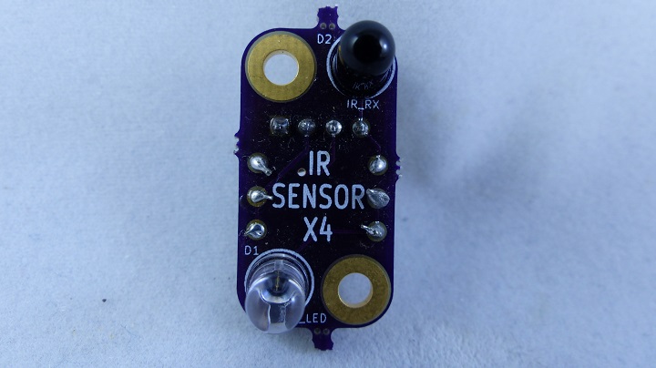
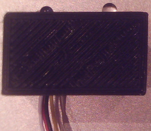
File:IR-Front.png File:IR-Back.png
This design consists of an Infrared Emitter and Infrared Receiver. The initial design was done with a http://www.radioshack.com/product/index.jsp?productId=2049723 Radio Shack P/N 276-142 which worked fairly well.
Using a 1M Ohm resistor as the Infrared Receiver bias value I got a nice voltage swing at various distances.
I didn't like the mismatch between the peak emitter (950mm) and received frequencies (850mm) and the cost of the Radio Shack solution is not cheap ($3.69) so I decided to look for new parts.
IR Emitter
LiteOn http://www.digikey.com/product-detail/en/HSDL-4261/516-1706-ND/724038 HSDL-4261
Infrared Emitters High Speed (LED), 5V, 45mW, 870nm, 26 Deg, T1-3/4 package (5mm)
Iforward	0.1	A
Pdiss	0.190	W	at 20 deg C
Vf-typ	1.7	V	at 100 mA
Voltage	5	V	Reverse
Vres	3.3	V	across resistor(s)
Res	35	Ohms
Resx2	82		R1,R2
ResX2/2	41
Iactual	0.080	A
Power	0.266	W
Power/2	0.133	W
Pow-res	0.25	W
Safety fact	0.531	W/W
Pwr-LED	0.137	W
Safety factor	0.720	W/W
IR Receiver
OSHRAM http://www.digikey.com/product-detail/en/SFH313FA/475-1080-ND/607289 SFH 313
Phototransistors NPN Phototransistor 70V 200mW 870nm
Irradiance units Ic units 10 mW/cm2 0.01 A 1 mW/cm2 0.001 A 0.01 mW/cm2 0.0001 A
Connector
J1 is a 4-pin 0.1" pitch header type of connector. The pinout is a modified GVS pinout.
Ground (Square pin) Voltage - Transmitter +5V Voltage - Receiver +5V Sensor Output
The purpose of having a separate transmitter and receiver voltage is two-fold. One it would allow the transmitter to be turned off and on conserving power and allowing for calibration at power-up. It needs to be noted that the drive current is greater than the current a microprocessor can directly drive.
The second purpose is to allow the analog reference voltage to be used for the receiver increasing noise immunity from the main power of the digital controller card(s).


