Difference between revisions of "JOYPAD"
Jump to navigation
Jump to search
Blwikiadmin (talk | contribs) (→Rev 2) |
Blwikiadmin (talk | contribs) (→Rev 2) |
||
| Line 48: | Line 48: | ||
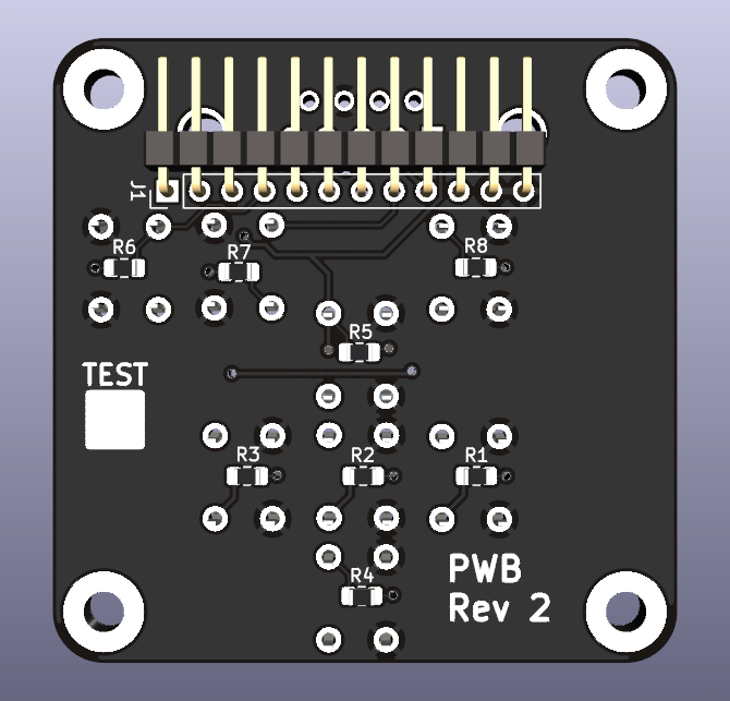
* Moved pullup resistors to the rear of the card in center of pushbutton footprints | * Moved pullup resistors to the rear of the card in center of pushbutton footprints | ||
| + | * Shown with header for ribbon cable | ||
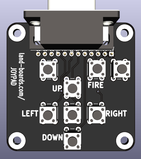
[[file:JoyPad_DB-9_REV2_REAR_Header-3D.png]] | [[file:JoyPad_DB-9_REV2_REAR_Header-3D.png]] | ||
Revision as of 16:23, 2 August 2022
Contents
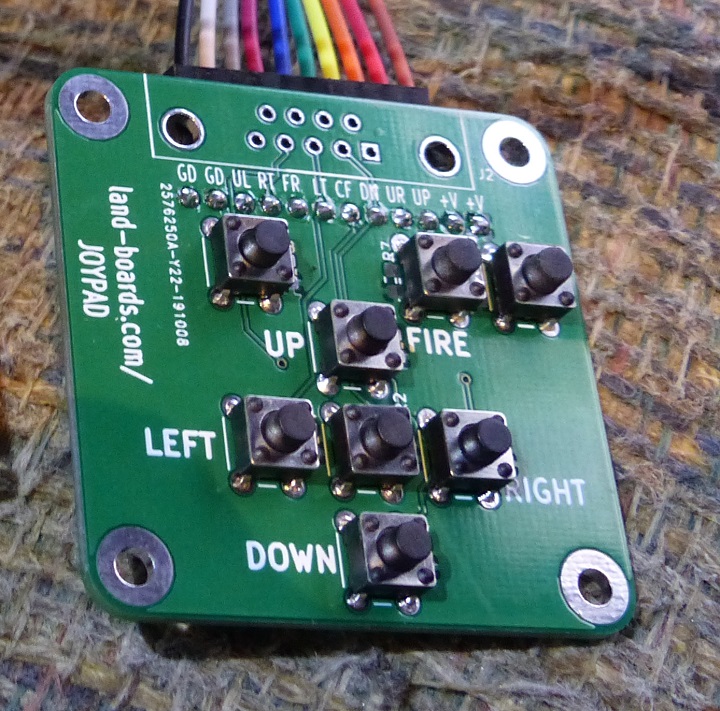
JOYPAD
- 8 Pushbutton Switches
- Up/Down/Left/Right/Center fire/3 others
- Connectors
- DB-9 Atari Joystick compatible
- 12 PIN 0.1" pitch
- 49x49mm card
- 4-40 mounting holes
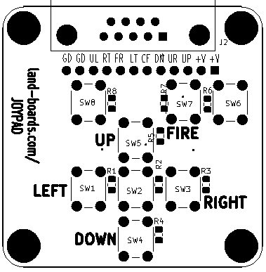
Connectors
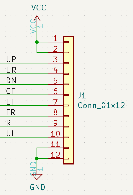
J1 - 12-Pin connector
- Right angle header on rear of card
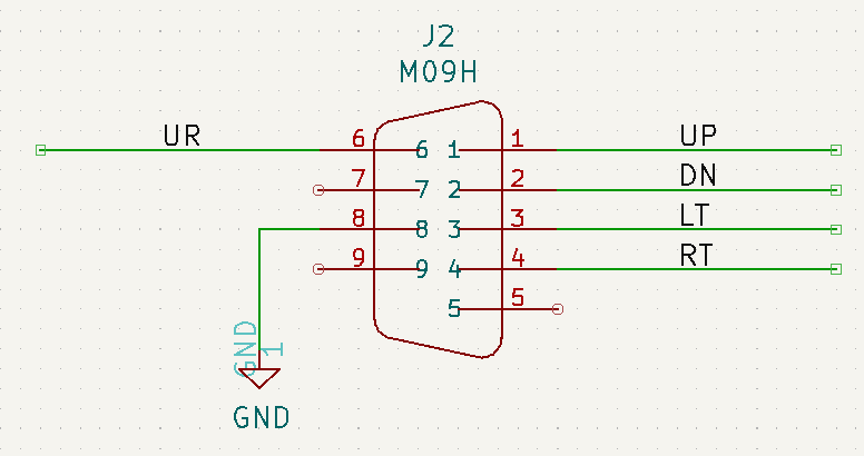
J2 - DB-9 connector
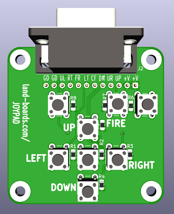
3D Image with DB-9
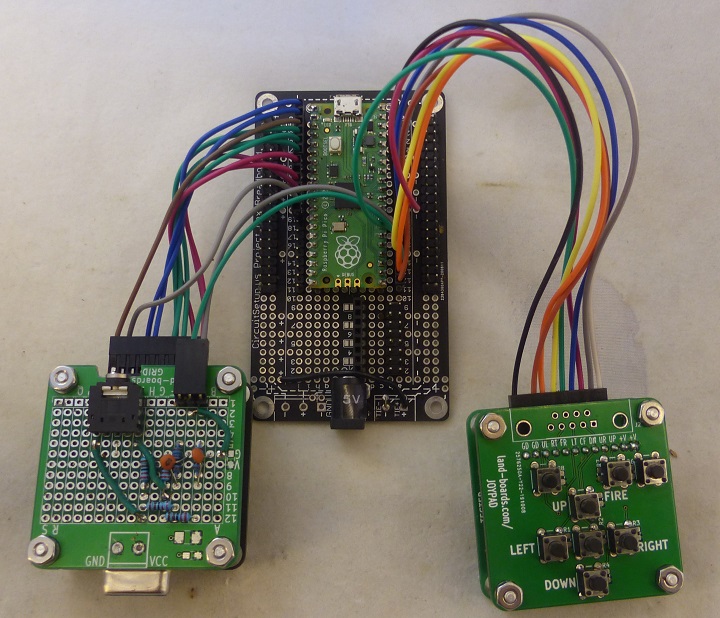
Application Example
Versions
Rev 2
- Change soldermask color to Black
- Moved DB-9 fire pin from Upper Right button to Fire button
- Changed to DB-9 Female
- Moved pullup resistors to the rear of the card in center of pushbutton footprints
- Shown with header for ribbon cable
Rev 1
- Works as-is
