MAX7219X4
Jump to navigation
Jump to search
Contents
Features
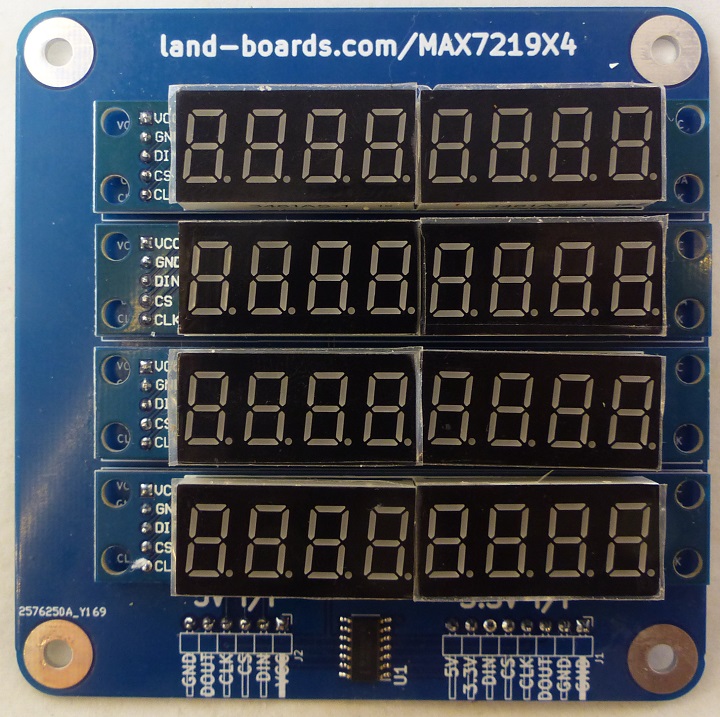
- (4) MAX7219 8 digits, 7 Segment display modules
- 32 digits
- 4 rows
- 8 digits per row
- Can display decimal, hex values, some text values
- Each display has 8 of 7 segment LED displays
- Uses "Blue" LED cards
- ebay search
- Not compatible with red modules
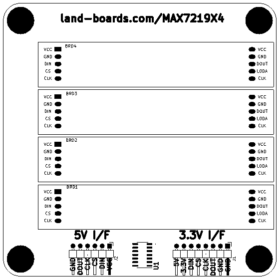
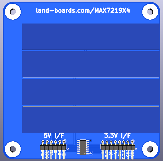
- Rev 1 has 3.3V interface operation (J1)
- 3.3V to 5V Level shifter
- Requires both 3.3V and 5V power supplies
- 8 pin connector
- Rev 2 has 3.3V signal levels J1 (as above) or 5V signal levels (adds J2)
- Only requires 5V for 5V operation
- Level translator can still be installed but right connector must be used
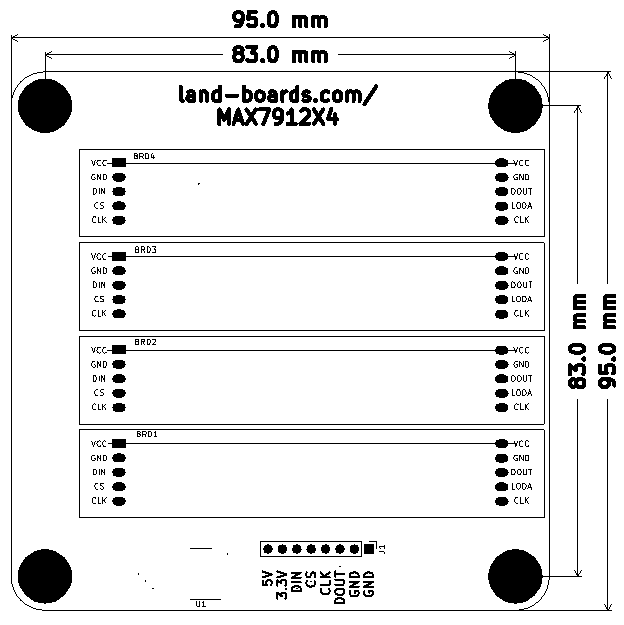
- 95x95mm ODAS form factor
- (4) 6-32 mounting holes
Connectors
- Only 1 of the 2 connectors J1 or J2 can be used at a time
J1 Connector
- 3.3V signal level
- 5V power to LEDs
- 1x8 right angle header mounted on rear of card
- GND
- GND
- DOUT
- CLK
- CS
- DIN
- +3.3V
- +5V
J2 (Rev 2 and higher)
- +5V
- DIN
- CS
- CLK
- DOUT
- GND
Programming
Arduino Programming
Arduino Drivers
- MAX7219X4 Land Boards Arduino GitHub repository
- Uses Arduino LedControl library
- Library writes to multiple 8-digit displays
- Pins
- Arduino UNO pin 12 is connected to the DataIn
- Arduino UNO pin 11 is connected to the CLK
- Arduino UNO pin 10 is connected to CS
- Uses Arduino LedControl library
Arduino Example Code
LBMAX7219X4_ADDR
- Runs on Arduino in a Box
- 3.3V signals level
- Also requires 5V for LEDs
- 5V on Arduino in a Box] DC Power Jack
- 5V picked off VFILT jack
- LBMAX7219X4_ADDR
- void writeHexDigit(uint8_t rowVal, uint8_t colVal, uint8_t digitVal) - Write Hexadecimal digit to location
- 8 columns, 4 rows
- rowVal = 0 is top row in display
- colVal = 0 = left character
LBMAX7219X4_ADDR_5V
- Same as LBMAX7219X4_ADDR
- Runs on 5V Arduino UNO
- LBMAX7219X4_ADDR_5V
- void writeHexDigit(uint8_t rowVal, uint8_t colVal, uint8_t digitVal) - Write Hexadecimal digit to location
- 8 columns, 4 rows
- rowVal = 0 is top row in display
- colVal = 0 = left character
LBMAX7219X4
- LBMAX7219X4
- Displays Land-Boards channel intro video across the LEDs on 4 rows of 8-digits MAX7219X4 card
- "LAND-" (first line)
- "BOARDS" (second line)
- "PRESENTS" (third line)
- "CARDS...", "AND CODE" (4th line)
CircuitPython Programming
class adafruit_max7219.bcddigits.BCDDigits(spi: SPI, cs: DigitalInOut, nDigits: int = 1)[source]
Basic support for display on a 7-Segment BCD display controlled by a Max7219 chip using SPI.
Parameters
spi (SPI) – an spi busio or spi bitbangio object
cs (DigitalInOut) – digital in/out to use as chip select signal
nDigits (int) – number of led 7-segment digits; default 1; max 8
VHDL Code
- MAX7219 VHDL code
- Instance
instance: MAX7219
    generic map(
            devices => 2,
            intensity => (16#1#, 16#3#)
        )
    port map (
            clk => clock,
            data_vector => x"FEDCBA9876543210",
            clk_out => MAX7219_CLK,
            data_out => MAX7219_DATA,
            load_out => MAX7219_LOAD,
            reset_n => globalResetN
        );
Test
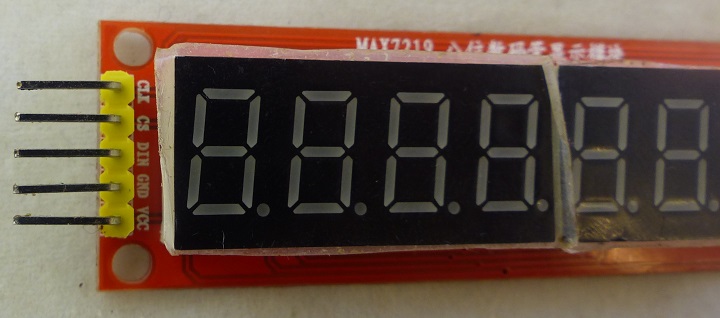
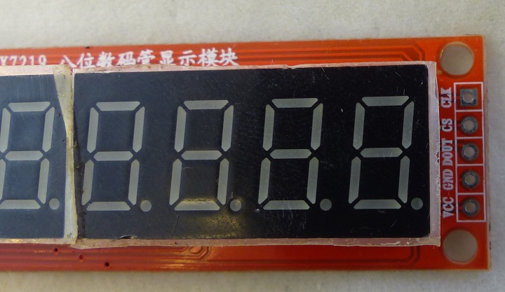
- Test single 8-digit modules
- Test MAX7219X4 card with (4) 8-digit modules
- Test 3.3V operation on J1 (Rev 1 or Rev 2 or higher)
- Test 5V operation on J2 (Rev 2 and higher)
Test Single MAX7219 Modules
| SenShld | Desc | MAX J1 | Color |
|---|---|---|---|
| VCC | VCC | 1 | RED |
| GND | GND | 2 | BLK |
| D12 | DATAIN | 3 | WHT |
| D10 | CS | 4 | BRN |
| D11 | CLK | 5 | YEL |
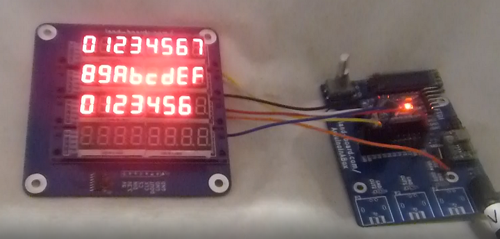
Test MAX7219X4 Card 3.3V
- ArduinoInABox
- Uses J1 Rev 1 UUT or Rev 2 UUT
- Wiring Table
| Signal | AiB | MAX7219X4 | Signal | Color |
|---|---|---|---|---|
| GND | J5-25 | J1-1 | GND | BLK |
| D10 | J5-21 | J1-5 | CS | WHT |
| D11 | J5-19 | J1-4 | CLK | YEL |
| D12 | J5-17 | J1-6 | DIN | BLU |
| +3.3V | J5-1 | J1-7 | +3.3V | RED |
| VFILT | J9-1 | J1-8 | 5V | ORG |
- Run Demo code
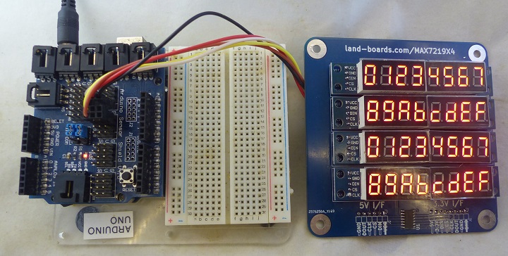
- Displays 0-7, 8-F twice
- Displays all 8's
Test MAX7219X4 Card 5V
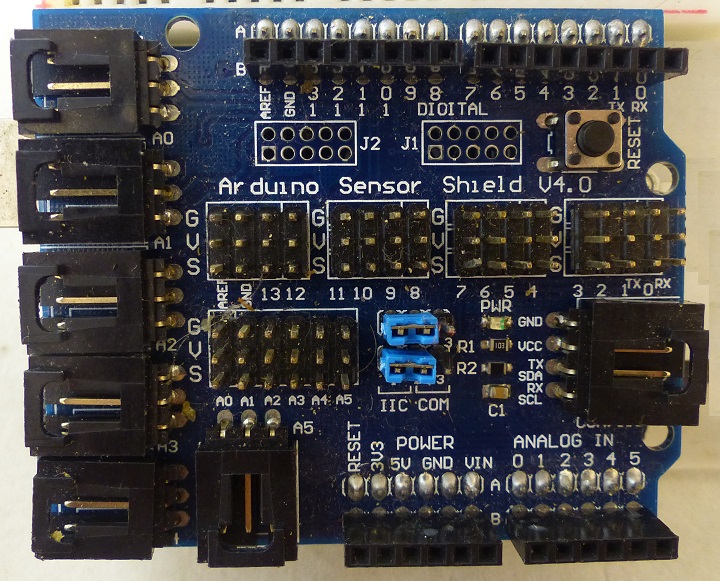
- Arduino UNO
- Arduino Sensor Shield
- Wiring Table
| Signal | Shield | MAX7219X4 | Signal | Color |
|---|---|---|---|---|
| GND | D12-S | J2-6 | GND | BLK |
| D10 | D10-S | J2-3 | CS | BRN |
| D11 | D11-S | J2-4 | CLK | YEL |
| D12 | D12-3 | J2-2 | DIN | WHT |
| 5V | D12-V | J2-1 | 5V | RED |
- Run Demo code
- Displays 0-7, 8-F twice
- Displays all 8's
"Red" Modules
- Incompatible pinouts
- Do not work with this card
- Flipped from blue modules
Mechanicals
Revision History
Rev 2
- Add 5V interface connector - J2
- Card can be driven from one of the two interfaces
- 5V interface does not require 3.3V
- Tested / works
- +5V
- DIN
- CS
- CLK
- DOUT
- GND
Rev 1
- Tested/works
- Requires 3.3V power and signal levels
- Requires 5V power

