Difference between revisions of "PiPicoMite01"
Blwikiadmin (talk | contribs) |
Blwikiadmin (talk | contribs) |
||
| Line 24: | Line 24: | ||
* 120mmx70mm outline | * 120mmx70mm outline | ||
* (4) 6-32 Mounting holes | * (4) 6-32 Mounting holes | ||
| + | |||
| + | === BASIC Interpreter === | ||
| + | |||
| + | The BASIC interpreter is full featured with double precision floating point, 64-bit integers and string variables, long variable names, arrays of floats, integers or strings with multiple dimensions, extensive string handling and user defined subroutines and functions. Typically it will execute a program up to 100,000 lines per second. MMBasic allows the embedding of compiled C programs for high performance functions and the running program can be protected from being listed or modified by a PIN number. | ||
| + | |||
| + | Support for all Raspberry Pi Pico input/output pins. These can be independently configured as digital input or output, analog input, frequency or period measurement and counting. Within MMBasic the I/O pins can be dynamically configured as inputs or outputs with or without pullups or pulldowns. | ||
| + | |||
| + | MMBasic commands will generate pulses and can be used to transfer data in parallel. Interrupts can be used to notify when an input pin has changed state. PWM outputs can be used to create various sounds, control servos or generate computer controlled voltages for driving equipment that uses an analogue input (eg, motor controllers). In addition, pins that are not exposed on the Raspberry Pi Pico can be accessed using MMBasic allowing it to be used on other modules that use the RP2040 processor. | ||
| + | |||
| + | TFT LCD display panels using SPI based interfaces are supported allowing the BASIC program to display text and draw lines, circles, boxes, etc in 65,535 colours. Resistive touch controllers on these panels are also supported allowing them to be used as sophisticated input devices. These LCD panels typically cost US$7 and provide a low cost, high tech graphical user interface. | ||
| + | |||
| + | Programming and control is done via the USB interface. All that is needed is a laptop/desktop computer running a VT100 terminal emulator. Once the program has been written and debugged the PicoMite can be instructed to automatically run the program on power up with no user intervention. Special software is not needed to develop programs. | ||
== Pin Marking on Rear == | == Pin Marking on Rear == | ||
Revision as of 20:48, 17 May 2022
Contents
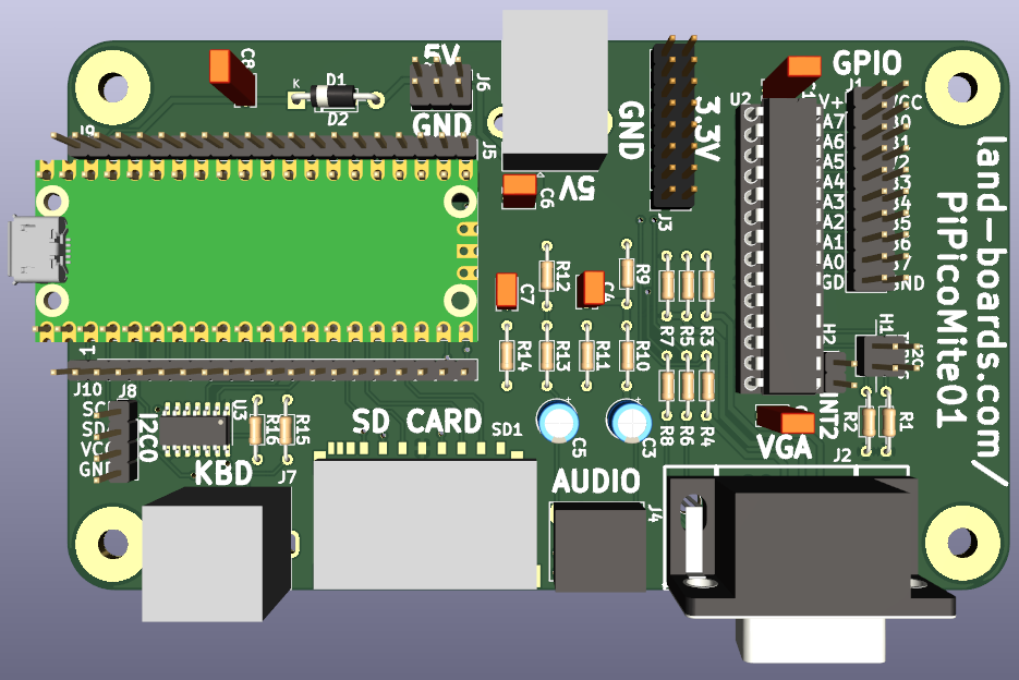
Features
- Raspberry Pi Pico
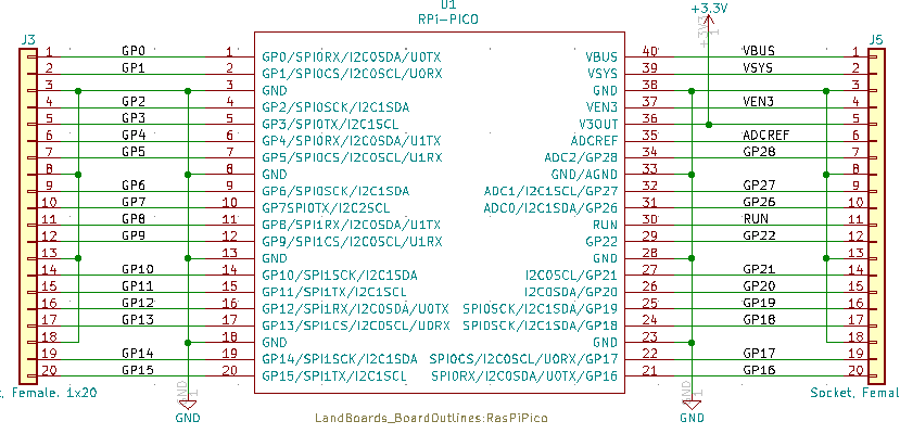
- All pins brought to header
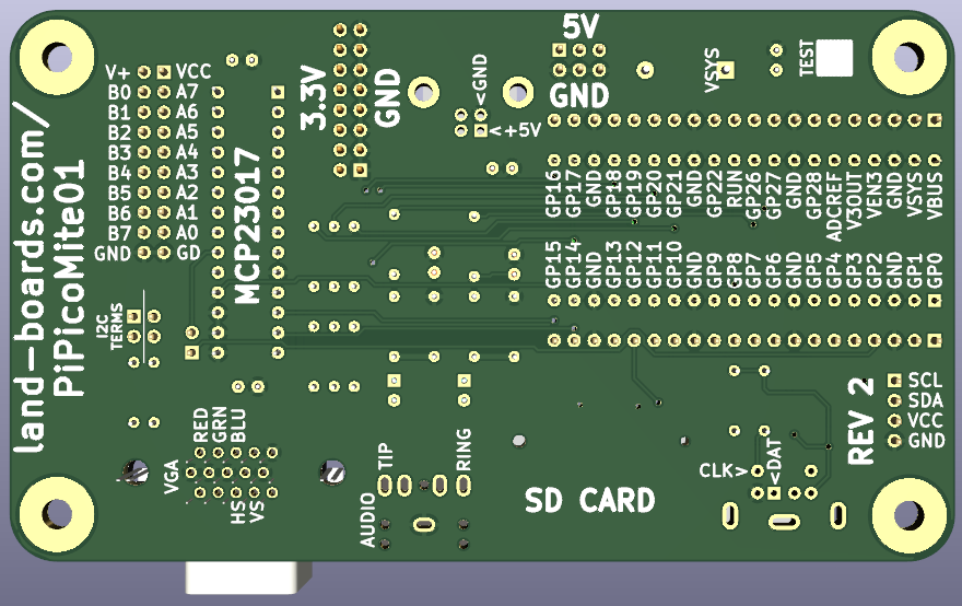
- Pin marking on rear
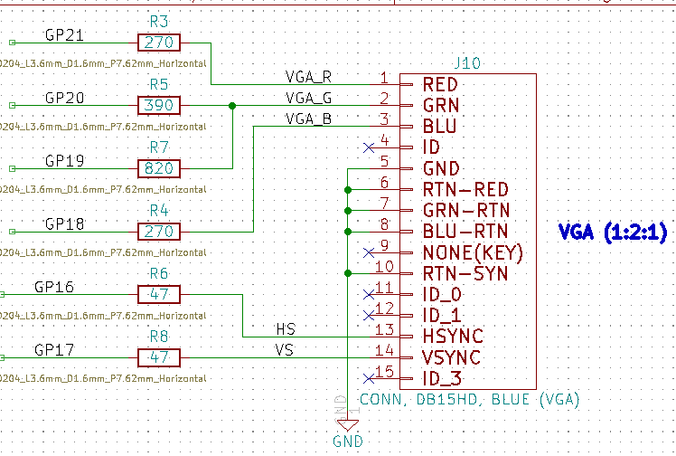
- VGA (1:2:1 - R:G:B)
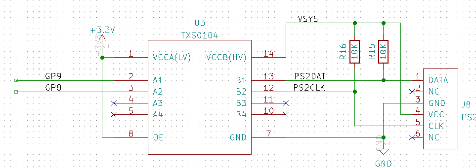
- PS/2 Keyboard
- 5V to keyboard with voltage translator
- SD Card
- Full size card
- Up to 32GB
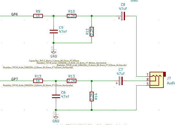
- Stereo audio
- 3.5mm jack
- 16-bit GPIO
- MCP23017 port expander
- I2C1
- 2x20 0.1" pitch header
- Jumper selectable terminators
- Power options
- 5V power input via USB B or 0.1" pitch header
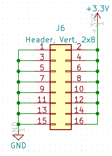
- 3.3V output header
- 120mmx70mm outline
- (4) 6-32 Mounting holes
BASIC Interpreter
The BASIC interpreter is full featured with double precision floating point, 64-bit integers and string variables, long variable names, arrays of floats, integers or strings with multiple dimensions, extensive string handling and user defined subroutines and functions. Typically it will execute a program up to 100,000 lines per second. MMBasic allows the embedding of compiled C programs for high performance functions and the running program can be protected from being listed or modified by a PIN number.
Support for all Raspberry Pi Pico input/output pins. These can be independently configured as digital input or output, analog input, frequency or period measurement and counting. Within MMBasic the I/O pins can be dynamically configured as inputs or outputs with or without pullups or pulldowns.
MMBasic commands will generate pulses and can be used to transfer data in parallel. Interrupts can be used to notify when an input pin has changed state. PWM outputs can be used to create various sounds, control servos or generate computer controlled voltages for driving equipment that uses an analogue input (eg, motor controllers). In addition, pins that are not exposed on the Raspberry Pi Pico can be accessed using MMBasic allowing it to be used on other modules that use the RP2040 processor.
TFT LCD display panels using SPI based interfaces are supported allowing the BASIC program to display text and draw lines, circles, boxes, etc in 65,535 colours. Resistive touch controllers on these panels are also supported allowing them to be used as sophisticated input devices. These LCD panels typically cost US$7 and provide a low cost, high tech graphical user interface.
Programming and control is done via the USB interface. All that is needed is a laptop/desktop computer running a VT100 terminal emulator. Once the program has been written and debugged the PicoMite can be instructed to automatically run the program on power up with no user intervention. Special software is not needed to develop programs.
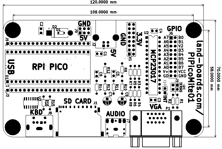
Pin Marking on Rear
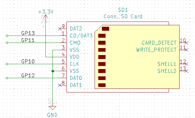
Schematic
Connectors
| GP | FUNCTION | PICO PIN |
|---|---|---|
| GP6 | AUDIO-L | 9 |
| GP7 | AUDIO-R | 10 |
| GND | AUDIO-GND | 8 |
| 3.3V | PS2_3.3V | |
| VSYS | PS2_5V | 39 |
| GP8 | PS2_CLK | 11 |
| GP9 | PS2_DATA | 12 |
| GND | PS2_GND | 13 |
| 3.3V | SD_3.3V | |
| GP12 | SD_MISO | 16 |
| GP11 | SD_MOSI | 15 |
| GP10 | SD_SCK | 14 |
| GP13 | SD_SLVSEL | 17 |
| GND | SD_GND | 18 |
| GP18 | VGA_BLU | 24 |
| GND | VGA_GND | 23 |
| GP20 | VGA_GRN_HI | 26 |
| GP19 | VGA_GRN_LO | 25 |
| GP16 | VGA_HSYNC | 21 |
| GP21 | VGA_RED | 27 |
| GP17 | VGA_VSYNC | 22 |
H1 - 3.3V Power Out
J1 - SD Card
J2 - USB B Power Connectors
- Full size USB B connector
- No USB signal connections, just used for power
J3/J5 Pico Connectors
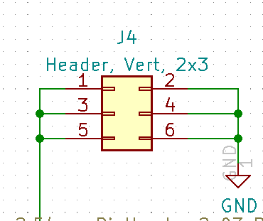
J4 - I2C Terminators
- Install shunts to terminate SDA, SCL signals
J6 - GPIO
J7 - Audio
J8 - PS/2 Keyboard
J9 - 5V Distribution
J10 - I2C INT
- Install jumper to connect Interrupt from MCP23017 to GP0 pin on Pico
- No Pull-up
P1 - VGA
Prototype Build
- Runs PicoMite (MaxiMite) BASIC (VGA, PS/2)
- Uses cards
- Pinouts
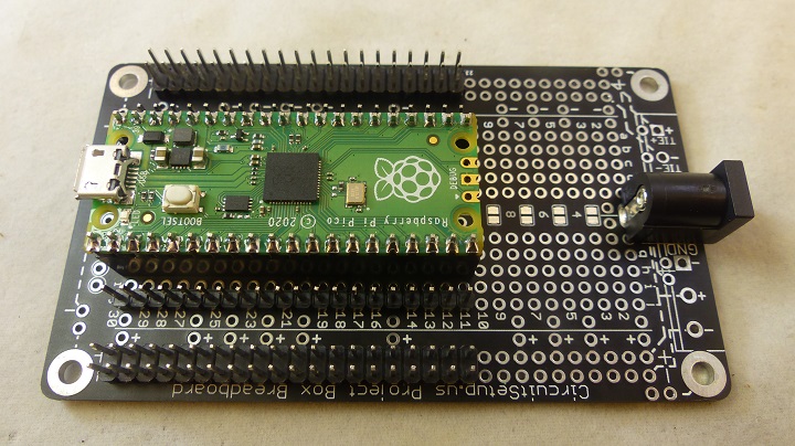
Raspberry Pi Pico in a Small Plastic Project Box
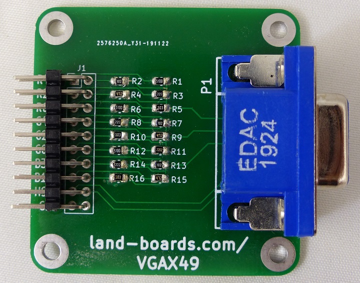
VGAX49
- VGAX49
- Resistors Values
- Selected for 0.7V output on analog RGB pins
- R12 = 270
- R6 = 390
- R7 = 820
- R1 = 270
| R,B | G RES | G | |||
|---|---|---|---|---|---|
| Rs | 75 | R1 | 390 | 75 | |
| Rm | 270 | R2 | 820 | 264.298 | |
| Vin | 3.3 | RM | 264.298 | 3.3 | |
| Vout | 0.717 | 0.729 | |||
| I (mA) | 9.57 | I (mA) | 9.73 |
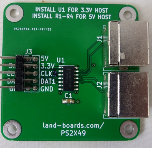
PS2X49
- PS2X49
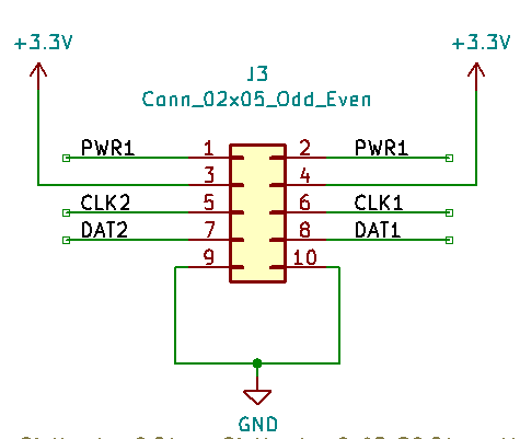
- PWR1 is the power to the PS/2 #1, #2 connectors (5V)
- +3.3V powers the TXS0104 translator
- Routing
- CLK1, DAT1 on J3 go to J1 (Purple)
- CLK2, DAT2 on J3 go to J2 (Not used)
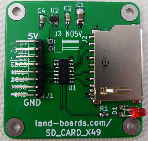
SD CARD X49
- SD CARD X49
- Install NO5V jumper
- Connect 3.3V power
- No 5V attached
- No U2 voltage regulator needed
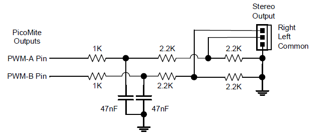
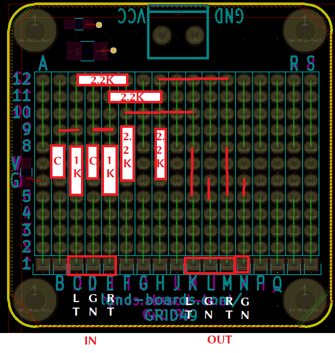
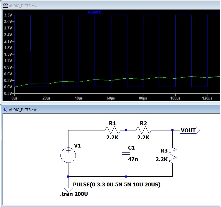
GRID49 - Audio Filter
- GRID49
- Audio filter circuit
- C1 = Audio_In-L
- D1 - GND
- E1 - Audio_In-R
Cabling
| FUNCTION | GP | PICO PIN | CARD | SIG | PIN | COLOUR |
|---|---|---|---|---|---|---|
| AUDIO-GND | GND | 8 | GRID49 | AUD-GND | D1 | BLK |
| AUDIO-L | GP6 | 9 | GRID49 | AUD-L | C1 | VIO |
| AUDIO-R | GP7 | 10 | GRID49 | AUD-R | E1 | YEL |
| PS2_CLK | GP8 | 11 | PS2X49 | CLK1 | 6 | VIO |
| PS2_DATA | GP9 | 12 | PS2X49 | DAT1 | 8 | YEL |
| PS2_GND | GND | 13 | PS2X49 | GND | 10 | BLK |
| SD_SCK | GP10 | 14 | SD_CARD_X49 | SCLK | 3 | VIO |
| SD_MOSI | GP11 | 15 | SD_CARD_X49 | MOSI | 4 | BLU |
| SD_MISO | GP12 | 16 | SD_CARD_X49 | MISO | 2 | YEL |
| SD_SLVSEL | GP13 | 17 | SD_CARD_X49 | -SDCS | 5 | GRY |
| SD_GND | GND | 18 | SD_CARD_X49 | GND | 1 | BLK |
| VGA_HSYNC | GP16 | 21 | VGA | HS | 17 | GRY |
| VGA_VSYNC | GP17 | 22 | VGA | VS | 18 | WHT |
| VGA_GND | GND | 23 | VGA | GND | 19 | BRN |
| VGA_BLU | GP18 | 24 | VGA | B4 | 12 | BLU |
| VGA_GRN_LO | GP19 | 25 | VGA | G4 | 7 | GRN |
| VGA_GRN_HI | GP20 | 26 | VGA | G5 | 6 | GRN |
| VGA_RED | GP21 | 27 | VGA | R4 | 1 | ORG |
| PS2_5V | VSYS | 39 | PS2X49 | PWR1 | 2 | ORG |
| PS2_3.3V | 3.3V | BUS | PS2X49 | 3.3V | 4 | RED |
| SD_3.3V | 3.3V | BUS | SD_CARD_X49 | 3.3V | 7 | RED |
Mechanicals
Applications
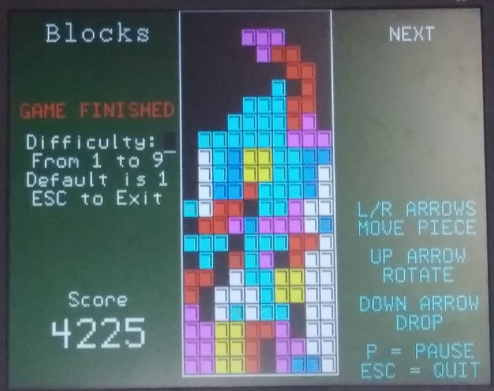
Tetris
> memory
Program:
  13K (10%) Program (485 lines)
  95K (90%) Free

RAM:
   8K ( 5%) 31 Variables
   0K ( 0%) General
 132K (95%) Free
