Difference between revisions of "SD CARD X49"
Jump to navigation
Jump to search
Blwikiadmin (talk | contribs) |
Blwikiadmin (talk | contribs) |
||
| Line 89: | Line 89: | ||
# 3.3V in/out | # 3.3V in/out | ||
# 5V in (for 5V host only) | # 5V in (for 5V host only) | ||
| + | |||
| + | {| class="wikitable" | ||
| + | ! Signal Name | ||
| + | ! SD Card pin | ||
| + | ! Color | ||
| + | ! Sensor Shield pin | ||
| + | |- | ||
| + | | GND | ||
| + | | 1 | ||
| + | | Green | ||
| + | | D13 GND | ||
| + | |- | ||
| + | | MISO | ||
| + | | 2 | ||
| + | | Violet | ||
| + | | D12 | ||
| + | |- | ||
| + | | SCLK | ||
| + | | 3 | ||
| + | | Grey | ||
| + | | D13 | ||
| + | |- | ||
| + | | MOSI | ||
| + | | 4 | ||
| + | | Brown | ||
| + | | D11 | ||
| + | |- | ||
| + | | SPI_SS | ||
| + | | 5 | ||
| + | | Yellow | ||
| + | | D10 | ||
| + | |- | ||
| + | | CARD_DETECT (no pull-up) | ||
| + | | 6 | ||
| + | | None | ||
| + | | N/A | ||
| + | |- | ||
| + | | 3.3V in/out | ||
| + | | 7 | ||
| + | | None | ||
| + | | N/A | ||
| + | |- | ||
| + | | 5V in (for 5V host only) | ||
| + | | 8 | ||
| + | | Orange | ||
| + | | D13 VCC | ||
| + | |- | ||
| + | |} | ||
=== Software === | === Software === | ||
Revision as of 20:35, 9 April 2022
Contents
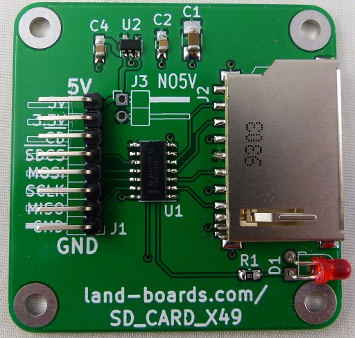
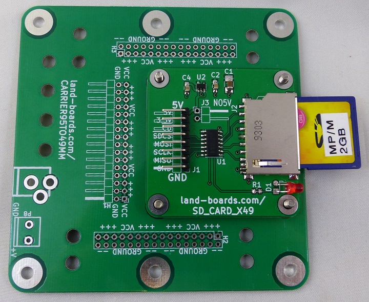
Features
- SD or SDHC card adapter
- 5V to 3.3V regulator
- 3.3V to 5V TXS0104E level shifter
- Activity LED
- 49 x 49 mm ODAS foprm factor
- (4) 4-40 mounting holes
Power Options
Important to properly set up the power option
- 3.3V Host
- Wire power to 3.3V position
- Install Jumper J3
- Leave 5V in pin open
- 5V Host
- Wire Power to 5V
- Leave 3.3V open
- Remove Jumper J3
J1 pinout
- GND
- MISO
- SCLK
- MOSI
- SPI_SS
- CARD_DETECT (no pull-up)
- 3.3V in/out
- 5V in (for 5V host only)
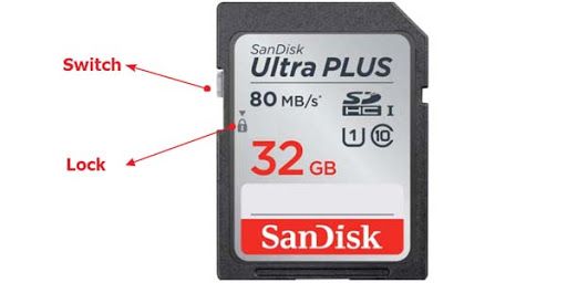
Lock/Unlock
- Set switch to not locked position
Used with Z80_PSOC card
- PSOC Pins
- MISO - PSOC pin 76
- MOSI - PSOC pin 77
- SCLK - PSOC pin 78
- SPI_SS - PSOC pin 79
Z80_PSOC - H3 Connector
- GND
- +5V
- SPI_SS - PSOC pin 79
- SCLK - PSOC pin 78
- MOSI - PSOC pin 77
- MISO - PSOC pin 76
Testing
- Testing is done using an Arduino at 5V
Hardware
- UUT
- Arduino UNO card
- FAT32 card with files on it
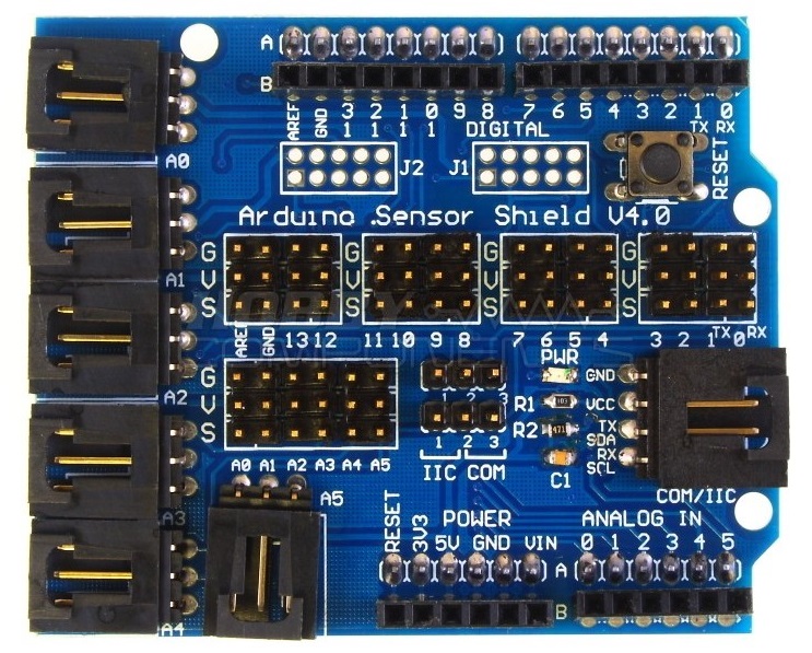
- Arduino Sensor Shield v4.0
- GVS connections
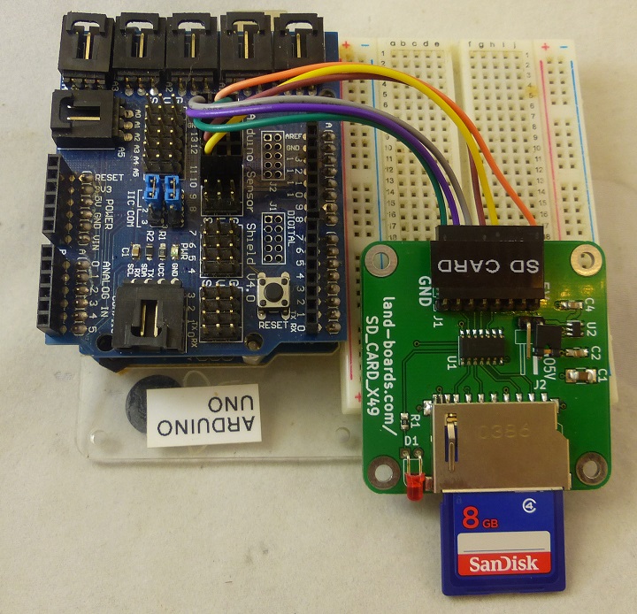
Test Cabling
- USB cable to PC
- 2x3 Dupont to D13/D12 and D11/D10
- 8 pin Dupont to SD card
- GND
- MISO
- SCLK
- MOSI
- SPI_SS
- CARD_DETECT (no pull-up)
- 3.3V in/out
- 5V in (for 5V host only)
| Signal Name | SD Card pin | Color | Sensor Shield pin |
|---|---|---|---|
| GND | 1 | Green | D13 GND |
| MISO | 2 | Violet | D12 |
| SCLK | 3 | Grey | D13 |
| MOSI | 4 | Brown | D11 |
| SPI_SS | 5 | Yellow | D10 |
| CARD_DETECT (no pull-up) | 6 | None | N/A |
| 3.3V in/out | 7 | None | N/A |
| 5V in (for 5V host only) | 8 | Orange | D13 VCC |
Software
Running
- Run Serial Monitor
- 9600 baud
- Prints directory to monitor
- Reset button on sensor shield to re-run

