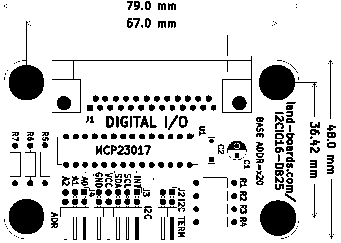
Difference between revisions of "I2CIO16-DB25"
Jump to navigation
Jump to search
Blwikiadmin (talk | contribs) |
Blwikiadmin (talk | contribs) |
||
| (41 intermediate revisions by the same user not shown) | |||
| Line 10: | Line 10: | ||
* I2C Interface - Two Wire Interface | * I2C Interface - Two Wire Interface | ||
** Can run at 400 KHz or faster | ** Can run at 400 KHz or faster | ||
| − | * I/O Connector is inexpensive/standard DB-25 | + | * I/O Connector is inexpensive/standard DB-25 female |
| + | ** Easy/quick to connect/disconnect | ||
| + | ** 16 Digital I/O lines | ||
| + | ** (3) Power, (3) Ground | ||
* Host connectors | * Host connectors | ||
** Daisy-chain I2C connector | ** Daisy-chain I2C connector | ||
** Address select jumper | ** Address select jumper | ||
| − | ** Expandable I2C via [[I2C-RPT]] - I2C Repeater | + | ** I2C base address = 0x20 |
| + | ** Jumpers allow card to be put at any I2C address in range 0x20-0x27 | ||
| + | ** Expandable I2C via [[I2C-RPT]] or [[I2C-RPT-08]] - I2C Repeater | ||
| + | *** Maximal example | ||
| + | **** 8 [[I2C-RPT-08]] Multiplexers | ||
| + | **** 8 cards per multiplexer | ||
| + | **** 16 I/O connections per card | ||
| + | **** 1,024 I/O | ||
** I2C Termination jumpers for end of I2C chain | ** I2C Termination jumpers for end of I2C chain | ||
* Power can be 3.3V or 5V | * Power can be 3.3V or 5V | ||
| − | * 6-32 Mounting holes | + | * Easy mounting options |
| + | ** Front panel cut-out | ||
| + | ** 6-32 Mounting holes | ||
| + | ** Boards can be stacked with 6-32 standoffs | ||
== Connectors == | == Connectors == | ||
| Line 25: | Line 38: | ||
=== J1 - DB-25 I/O Connector === | === J1 - DB-25 I/O Connector === | ||
| − | * Pins 1, 2, 14 are connected to | + | * DB-25 female pinout from the front of the card/connector |
| − | * Pins 12, 13, 25 are connected to | + | |
| − | * Pins | + | [[File:DB25_F.png]] |
| + | |||
| + | * Pins 1, 2, 14 are connected to Power | ||
| + | * Pins 12, 13, 25 are connected to Ground | ||
| + | * Pins 11, 15, 24 are not used | ||
| + | |||
| + | [[file:I2CIO16-DB25_J1.PNG]] | ||
=== J2 - I2C Termination === | === J2 - I2C Termination === | ||
| Line 33: | Line 52: | ||
* Two of two position headers | * Two of two position headers | ||
* Install headers in each position to terminate I2C line | * Install headers in each position to terminate I2C line | ||
| − | * There should only be one set of I2C termination jumpers and termination should be at the end of the I2C | + | * There should only be one set of I2C termination jumpers and termination should be at the end of the I2C daisy-chain |
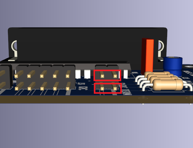
| − | * Side by side | + | * Side-by-side horizontal orientation (opposite of Address jumpers orientation) |
[[file:I2CIO16-DB25_I2C_term_Jumpers.png]] | [[file:I2CIO16-DB25_I2C_term_Jumpers.png]] | ||
| Line 52: | Line 71: | ||
=== J4 - Address Select === | === J4 - Address Select === | ||
| + | |||
| + | [[file:I2CIO16-DB25_J4.PNG]] | ||
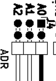
* Sets the I2C offset address of the card | * Sets the I2C offset address of the card | ||
| + | * Install jumper for Ax = 0, remove jumper for Ax = 1 | ||
* Three bit address A1, A2 | * Three bit address A1, A2 | ||
| Line 60: | Line 82: | ||
# A2 | # A2 | ||
| − | * | + | {| class="wikitable" |
| + | ! I2C Address | ||
| + | ! J4(A2) | ||
| + | ! J4(A1) | ||
| + | ! J4(A0) | ||
| + | |- | ||
| + | | 0x0 | ||
| + | | In | ||
| + | | In | ||
| + | | In | ||
| + | |- | ||
| + | | 0x1 | ||
| + | | In | ||
| + | | In | ||
| + | | Out | ||
| + | |- | ||
| + | | 0x2 | ||
| + | | In | ||
| + | | Out | ||
| + | | In | ||
| + | |- | ||
| + | | 0x3 | ||
| + | | In | ||
| + | | Out | ||
| + | | Out | ||
| + | |- | ||
| + | | 0x4 | ||
| + | | Out | ||
| + | | In | ||
| + | | In | ||
| + | |- | ||
| + | | 0x5 | ||
| + | | Out | ||
| + | | In | ||
| + | | Out | ||
| + | |- | ||
| + | | 0x6 | ||
| + | | Out | ||
| + | | Out | ||
| + | | In | ||
| + | |- | ||
| + | | 0x7 | ||
| + | | Out | ||
| + | | Out | ||
| + | | Out | ||
| + | |- | ||
| + | |} | ||
| + | |||
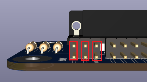
| + | * Jumper orientation | ||
[[file:I2CIO16-DB25_I2C_addr_Jumpers.png]] | [[file:I2CIO16-DB25_I2C_addr_Jumpers.png]] | ||
| Line 74: | Line 144: | ||
=== Arduino Drivers === | === Arduino Drivers === | ||
| − | * [https://github.com/ | + | * [https://github.com/land-boards/lb-Arduino-Code/blob/master/LBCards/I2CIO16DB25 Land Boards Arduino Driver Code/Example Software] for the PROTO16-I2C Card |
* [https://github.com/adafruit/Adafruit-MCP23017-Arduino-Library Adafruit MCP23017 Arduino Driver] | * [https://github.com/adafruit/Adafruit-MCP23017-Arduino-Library Adafruit MCP23017 Arduino Driver] | ||
| Line 85: | Line 155: | ||
==== MMBASIC ==== | ==== MMBASIC ==== | ||
| − | * [https://github.com/land-boards/RasPiPico/blob/main/PicoMite_MMBASIC/PicoMite_VGA/Land%20Boards%20BASIC%20Programs/lbcards/GPIO16/ | + | * [https://github.com/land-boards/RasPiPico/blob/main/PicoMite_MMBASIC/PicoMite_VGA/Land%20Boards%20BASIC%20Programs/lbcards/GPIO16/I2CIO16-DB25.bas I2CIO16-DB25.bas] code to bounce an LED |
** Runs on [[PiPicoMite01]] or [[PiPicoMite02]] card | ** Runs on [[PiPicoMite01]] or [[PiPicoMite02]] card | ||
| Line 105: | Line 175: | ||
* [http://lxr.free-electrons.com/source/drivers/gpio/gpio-mcp23s08.c Linux Driver source code] | * [http://lxr.free-electrons.com/source/drivers/gpio/gpio-mcp23s08.c Linux Driver source code] | ||
| + | |||
| + | == Mechanicals == | ||
| + | |||
| + | [[file:I2CIO16-DB25_Mechs.PNG]] | ||
== Factory Acceptance Tests == | == Factory Acceptance Tests == | ||
| − | + | === Setup === | |
* Unit Under Test (UUT) | * Unit Under Test (UUT) | ||
| − | * Runs on [[ | + | * Runs on [[PiPicoMite02 Based Test Station]] |
| − | * | + | ** [[PiPicoMite02]] |
| − | * I2C cable to UUT | + | ** [[LED-32]] card |
| − | * | + | *** Uses 16 LEDs for the digital I/O and 3 for power |
| − | * [[DB25RIBBON]] plugged into UUT | + | |
| + | [[File:PiPicoMite02_TestStation_Cables_P18298-720px.jpg]] | ||
| + | |||
| + | * I2C cable from [[PiPicoMite02 Based Test Station]] to UUT | ||
| + | * Cables/Adapter | ||
| + | ** [[DB25RIBBON]] with male connector plugged into UUT | ||
| + | |||
| + | ==== Ribbon Cable Wiring ==== | ||
| + | |||
* Cable between [[LED-32]] and [[DB25RIBBON]] | * Cable between [[LED-32]] and [[DB25RIBBON]] | ||
| − | * Code bounces LED | + | {| class="wikitable" |
| + | ! J1 | ||
| + | ! DB25 | ||
| + | ! I2CIO16 | ||
| + | ! LED-32 | ||
| + | ! | ||
| + | ! J1 | ||
| + | ! DB25 | ||
| + | ! I2CIO16 | ||
| + | ! LED-32 | ||
| + | |- | ||
| + | | 25 | ||
| + | | 1 | ||
| + | | GND | ||
| + | | | ||
| + | | | ||
| + | | 26 | ||
| + | | | ||
| + | | N/C | ||
| + | | | ||
| + | |- | ||
| + | | 23 | ||
| + | | 2 | ||
| + | | GND | ||
| + | | | ||
| + | | | ||
| + | | 24 | ||
| + | | 14 | ||
| + | | GND | ||
| + | | | ||
| + | |- | ||
| + | | 21 | ||
| + | | 3 | ||
| + | | GP0 | ||
| + | | D15 | ||
| + | | | ||
| + | | 22 | ||
| + | | 15 | ||
| + | | N/C | ||
| + | | | ||
| + | |- | ||
| + | | 19 | ||
| + | | 4 | ||
| + | | GP1 | ||
| + | | D14 | ||
| + | | | ||
| + | | 20 | ||
| + | | 16 | ||
| + | | GP15 | ||
| + | | D24 | ||
| + | |- | ||
| + | | 17 | ||
| + | | 5 | ||
| + | | GP2 | ||
| + | | D13 | ||
| + | | | ||
| + | | 18 | ||
| + | | 17 | ||
| + | | GP14 | ||
| + | | D25 | ||
| + | |- | ||
| + | | 15 | ||
| + | | 6 | ||
| + | | GP3 | ||
| + | | D12 | ||
| + | | | ||
| + | | 16 | ||
| + | | 18 | ||
| + | | GP13 | ||
| + | | D26 | ||
| + | |- | ||
| + | | 13 | ||
| + | | 7 | ||
| + | | GP4 | ||
| + | | D11 | ||
| + | | | ||
| + | | 14 | ||
| + | | 19 | ||
| + | | GP12 | ||
| + | | D27 | ||
| + | |- | ||
| + | | 11 | ||
| + | | 8 | ||
| + | | GP5 | ||
| + | | D10 | ||
| + | | | ||
| + | | 12 | ||
| + | | 20 | ||
| + | | GP11 | ||
| + | | D28 | ||
| + | |- | ||
| + | | 9 | ||
| + | | 9 | ||
| + | | GP6 | ||
| + | | D9 | ||
| + | | | ||
| + | | 10 | ||
| + | | 21 | ||
| + | | GP10 | ||
| + | | D29 | ||
| + | |- | ||
| + | | 7 | ||
| + | | 10 | ||
| + | | GP7 | ||
| + | | D8 | ||
| + | | | ||
| + | | 8 | ||
| + | | 22 | ||
| + | | GP9 | ||
| + | | D30 | ||
| + | |- | ||
| + | | 5 | ||
| + | | 11 | ||
| + | | N/C | ||
| + | | | ||
| + | | | ||
| + | | 6 | ||
| + | | 23 | ||
| + | | GP8 | ||
| + | | D31 | ||
| + | |- | ||
| + | | 3 | ||
| + | | 12 | ||
| + | | +3.3V | ||
| + | | D0 | ||
| + | | | ||
| + | | 4 | ||
| + | | 24 | ||
| + | | N/C | ||
| + | | | ||
| + | |- | ||
| + | | 1 | ||
| + | | 13 | ||
| + | | +3.3V | ||
| + | | D1 | ||
| + | | | ||
| + | | 2 | ||
| + | | 25 | ||
| + | | +3.3V | ||
| + | | D3 | ||
| + | |- | ||
| + | |} | ||
| + | |||
| + | === Run Test Code === | ||
| + | |||
| + | * Runs [https://github.com/land-boards/RasPiPico/blob/main/PicoMite_MMBASIC/PicoMite_VGA/Land%20Boards%20BASIC%20Programs/lbcards/GPIO16/I2CIO16-DB25.bas I2CIO16-DB25.bas] code | ||
| + | * Run on [[PiPicoMite02 Based Test Station]] | ||
| + | |||
| + | <pre> | ||
| + | chdir "/lbcards/GPIO16" | ||
| + | load "I2CIO16-DB25.bas" | ||
| + | run | ||
| + | </pre> | ||
| + | |||
| + | * Result | ||
| + | ** Code bounces LED | ||
| + | ** 3 Power LEDs should be constantly be lit | ||
== Issues == | == Issues == | ||
| − | == | + | === Rev 1 === |
| + | |||
| + | * No issues | ||
| + | * Card is fully functional | ||
| + | |||
| + | == I2CIO16-DB25 Rev 1 Assembly Sheet == | ||
* [[I2CIO16-DB25 Rev 1 Assembly Sheet]] | * [[I2CIO16-DB25 Rev 1 Assembly Sheet]] | ||
Latest revision as of 11:49, 21 June 2022
Contents
Features
- 16-bit Digital I/O card
- MCP23017 16-bit I2C I/O Expander
- Strong library support for all major microprocessors for MCP23017
- I2C Interface - Two Wire Interface
- Can run at 400 KHz or faster
- I/O Connector is inexpensive/standard DB-25 female
- Easy/quick to connect/disconnect
- 16 Digital I/O lines
- (3) Power, (3) Ground
- Host connectors
- Daisy-chain I2C connector
- Address select jumper
- I2C base address = 0x20
- Jumpers allow card to be put at any I2C address in range 0x20-0x27
- Expandable I2C via I2C-RPT or I2C-RPT-08 - I2C Repeater
- Maximal example
- 8 I2C-RPT-08 Multiplexers
- 8 cards per multiplexer
- 16 I/O connections per card
- 1,024 I/O
- Maximal example
- I2C Termination jumpers for end of I2C chain
- Power can be 3.3V or 5V
- Easy mounting options
- Front panel cut-out
- 6-32 Mounting holes
- Boards can be stacked with 6-32 standoffs
Connectors
J1 - DB-25 I/O Connector
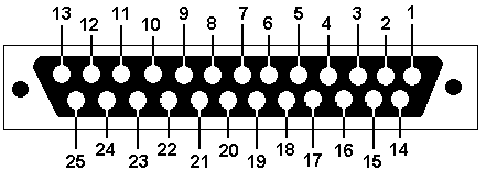
- DB-25 female pinout from the front of the card/connector
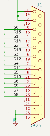
- Pins 1, 2, 14 are connected to Power
- Pins 12, 13, 25 are connected to Ground
- Pins 11, 15, 24 are not used
J2 - I2C Termination
- Two of two position headers
- Install headers in each position to terminate I2C line
- There should only be one set of I2C termination jumpers and termination should be at the end of the I2C daisy-chain
- Side-by-side horizontal orientation (opposite of Address jumpers orientation)
J3 - I2C
- Connector is 2x5 of 0.1" header
- Intended to be used for I2C daisy-chain of 4-pin cabling
- Power can be attached to the connector or power can be provided to the card via the J1 power connector
- May still want to connect ground
- INT
- SCL
- SDA
- VCC
- GND
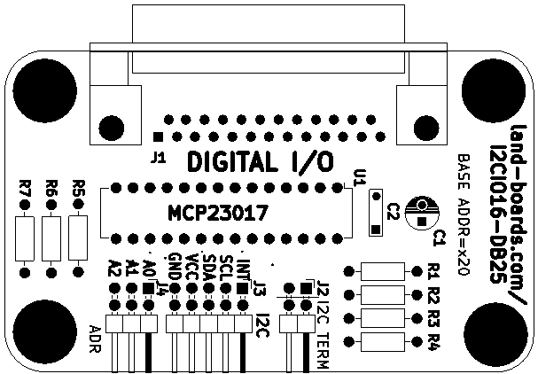
J4 - Address Select
- Sets the I2C offset address of the card
- Install jumper for Ax = 0, remove jumper for Ax = 1
- Three bit address A1, A2
- A0
- A1
- A2
| I2C Address | J4(A2) | J4(A1) | J4(A0) |
|---|---|---|---|
| 0x0 | In | In | In |
| 0x1 | In | In | Out |
| 0x2 | In | Out | In |
| 0x3 | In | Out | Out |
| 0x4 | Out | In | In |
| 0x5 | Out | In | Out |
| 0x6 | Out | Out | In |
| 0x7 | Out | Out | Out |
- Jumper orientation
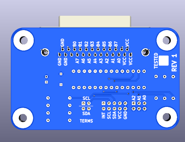
Rear Side Marking
MCP23017 Drivers
There are quite a I2C drivers for every major microcontroller (Arduino, Raspberry Pi, BeagleBone, etc).
Arduino Drivers
- Land Boards Arduino Driver Code/Example Software for the PROTO16-I2C Card
- Adafruit MCP23017 Arduino Driver
Raspberry Pi Drivers
Raspberry Pi Pico
MMBASIC
- I2CIO16-DB25.bas code to bounce an LED
- Runs on PiPicoMite01 or PiPicoMite02 card
BeagleBone Black Drivers
ESP32 MicroPython Drivers
PyBoard MicroPython Drivers
Linux Drivers
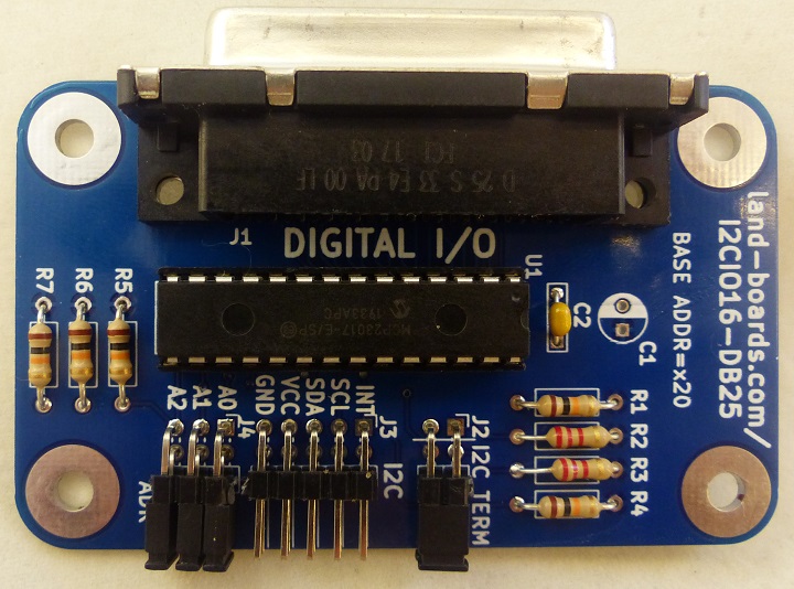
Mechanicals
Factory Acceptance Tests
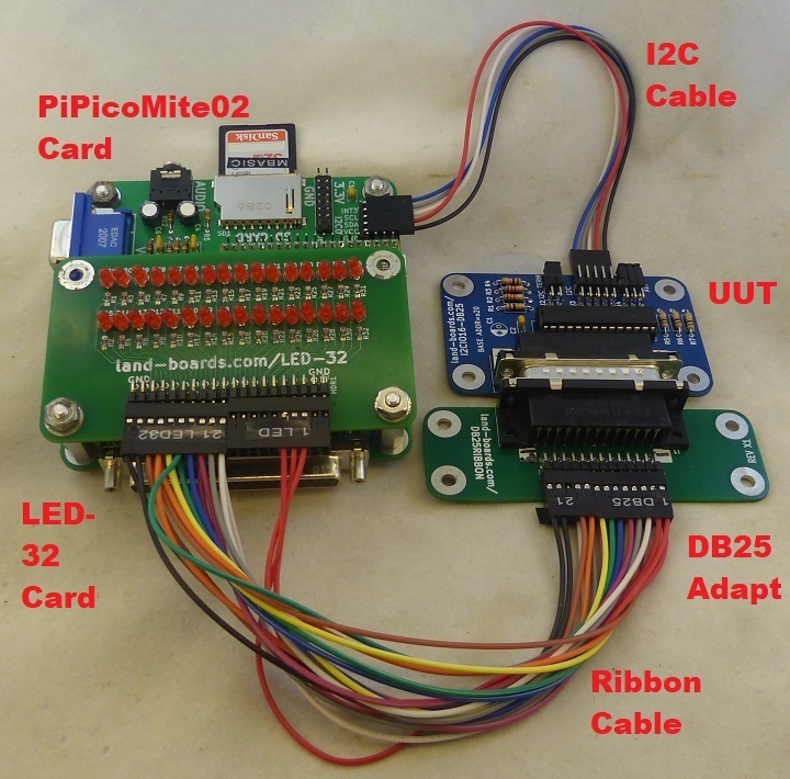
Setup
- Unit Under Test (UUT)
- Runs on PiPicoMite02 Based Test Station
- PiPicoMite02
- LED-32 card
- Uses 16 LEDs for the digital I/O and 3 for power
- I2C cable from PiPicoMite02 Based Test Station to UUT
- Cables/Adapter
- DB25RIBBON with male connector plugged into UUT
Ribbon Cable Wiring
- Cable between LED-32 and DB25RIBBON
| J1 | DB25 | I2CIO16 | LED-32 | J1 | DB25 | I2CIO16 | LED-32 | |
|---|---|---|---|---|---|---|---|---|
| 25 | 1 | GND | 26 | N/C | ||||
| 23 | 2 | GND | 24 | 14 | GND | |||
| 21 | 3 | GP0 | D15 | 22 | 15 | N/C | ||
| 19 | 4 | GP1 | D14 | 20 | 16 | GP15 | D24 | |
| 17 | 5 | GP2 | D13 | 18 | 17 | GP14 | D25 | |
| 15 | 6 | GP3 | D12 | 16 | 18 | GP13 | D26 | |
| 13 | 7 | GP4 | D11 | 14 | 19 | GP12 | D27 | |
| 11 | 8 | GP5 | D10 | 12 | 20 | GP11 | D28 | |
| 9 | 9 | GP6 | D9 | 10 | 21 | GP10 | D29 | |
| 7 | 10 | GP7 | D8 | 8 | 22 | GP9 | D30 | |
| 5 | 11 | N/C | 6 | 23 | GP8 | D31 | ||
| 3 | 12 | +3.3V | D0 | 4 | 24 | N/C | ||
| 1 | 13 | +3.3V | D1 | 2 | 25 | +3.3V | D3 |
Run Test Code
- Runs I2CIO16-DB25.bas code
- Run on PiPicoMite02 Based Test Station
chdir "/lbcards/GPIO16"
load "I2CIO16-DB25.bas"
run
- Result
- Code bounces LED
- 3 Power LEDs should be constantly be lit
Issues
Rev 1
- No issues
- Card is fully functional

