Difference between revisions of "Z80-MBC2 Build Notes"
Jump to navigation
Jump to search
Blwikiadmin (talk | contribs) (→Parts) |
Blwikiadmin (talk | contribs) (→Parts) |
||
| Line 7: | Line 7: | ||
* [https://j4f.info/z80-mbc2 Z80-MBC2] card | * [https://j4f.info/z80-mbc2 Z80-MBC2] card | ||
** Z80 CPU CMOS (Z84C00) 8Mhz or greater - I used 20 MHz | ** Z80 CPU CMOS (Z84C00) 8Mhz or greater - I used 20 MHz | ||
| − | ** Atmega32A | + | ** [https://www.mouser.com/ProductDetail/Microchip-Technology-Atmel/ATMEGA32A-PU?qs=6WoM%2FY8vMbadJ8khIfKCsQ%3D%3D Atmega32A] |
** TC551001-70 (128kB RAM) | ** TC551001-70 (128kB RAM) | ||
** I used [https://www.mouser.com/ProductDetail/913-AS6C1008-55PIN AS6C1008-55PIN] since it is available on Mouser and Digikey | ** I used [https://www.mouser.com/ProductDetail/913-AS6C1008-55PIN AS6C1008-55PIN] since it is available on Mouser and Digikey | ||
** 74HC00 | ** 74HC00 | ||
| − | * I added the optional MCP23017 for GPIO | + | * I added the optional [https://www.mouser.com/ProductDetail/Microchip-Technology-Atmel/MCP23017-E-SP?qs=usxtMOJb1RyESXZDw7ia5A%3D%3D MCP23017] for GPIO |
* External cards | * External cards | ||
** External RTC | ** External RTC | ||
Revision as of 19:53, 5 September 2022
Contents
Parts
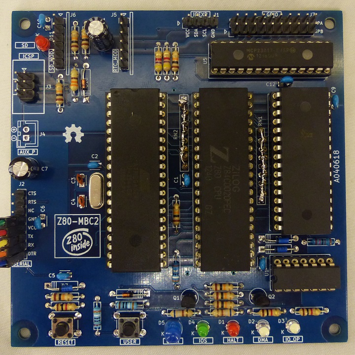
- Z80-MBC2 card
- Z80 CPU CMOS (Z84C00) 8Mhz or greater - I used 20 MHz
- Atmega32A
- TC551001-70 (128kB RAM)
- I used AS6C1008-55PIN since it is available on Mouser and Digikey
- 74HC00
- I added the optional MCP23017 for GPIO
- External cards
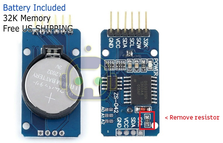
- External RTC
- External SD card
- Runs Petit FAT File System - Loads FAT32 SD cards loaded in Windows
- External USB-Serial adapter
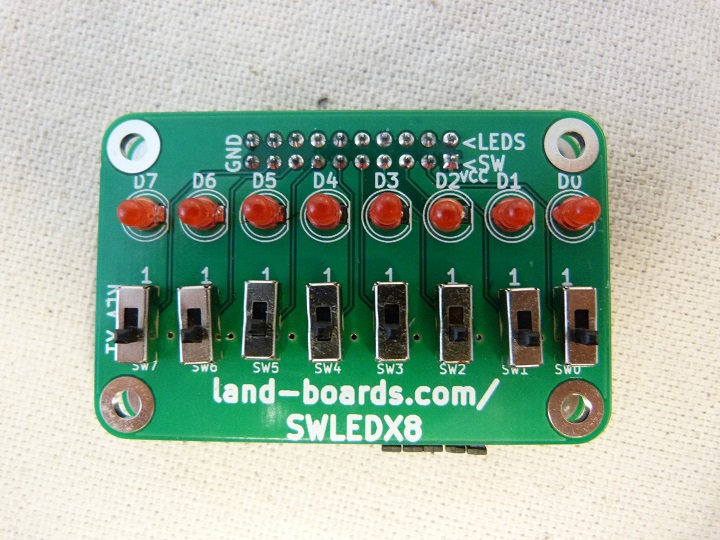
- SWLEDX8 - LEDs card
- Custom wiring, no slide switches
- Bare Board on ebay - $8 shipping included
- Arrived in a couple of days
- Kit for sale
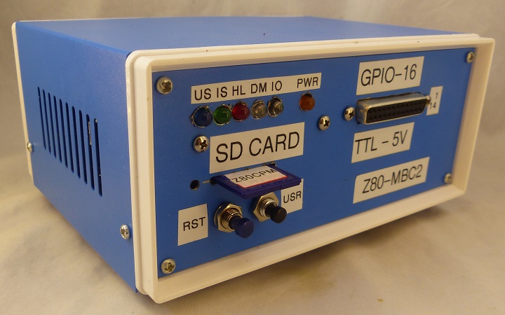
- Enclosure
Licensing and Credits
- All the project files (SW & HW) are licensed under GPL v3.
- If you use this material in any way a reference to the author (me :-) ) will be appreciated.
- CP/M seems to be Open Source now (see here).
- Basic stand-alone interpreter was an adaptation from Grant Searle work.
- Forth stand-alone interpreter was originally ported to the Z80-MBC by Bill Westfield.
- UCSD Pascal was ported by Michel Bernard.
- Collapse OS was designed and ported by Virgil Dupras.
Reference Docs
- An Easy to Build Real Homemade Computer: Z80-MBC2! - Instructable was helpful
- Hackaday project with files
- Our GitHub Repo
- Facebook page - Great group
Build Notes
- All through hole construction
- Build took less than 2 hours
- Used mostly junk box parts
- 20 MHz Z80 (Runs ar 4 or 8 MHz)
- Purchased alternate SRAM
- Purchased DIP machined sockets (I usually go cheaper but these were very nice)
- Forgot to buy SIP resistors
- Made my own SIP resistors
- Pin 1 (boxed pin on silkscreen is the common
- Used 1/8W resistors vertically mounted
- 5mm LEDs fit into 3mm hole spacing
- I didn't have a 3mm Blue so I used 5mm
- Ordered DS3231 AT24C32 IIC Precision Real Time Clock RTC Memory Module for Arduino
Negatives
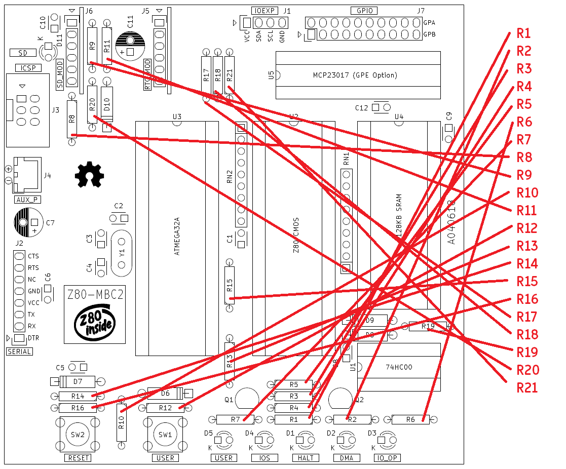
- Ref des are not top-bottom or left-right
- Struggled to find some of the resistors on the PCB
- PDF Assembly drawing text is not searchable
- Serial port marking correlated to the FTDI card end not referenced from card internal
Enclosure
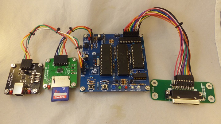
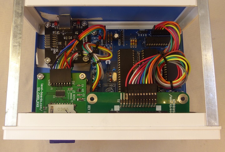
Card Set
- Z80-MBC2
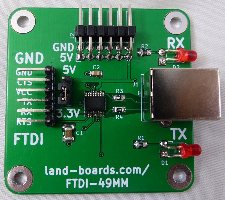
- FTDI card
- SD card
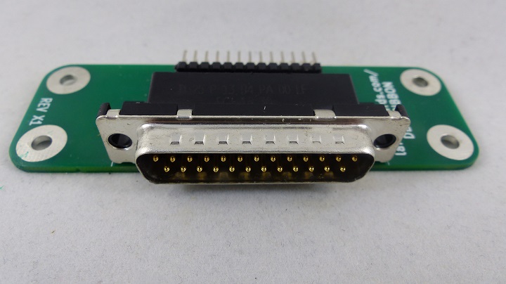
- DB-25 to Ribbon cable card
- SWLEDX8 - LEDs mounted to front panel through this card (not shown in photo)
Front View
Top View
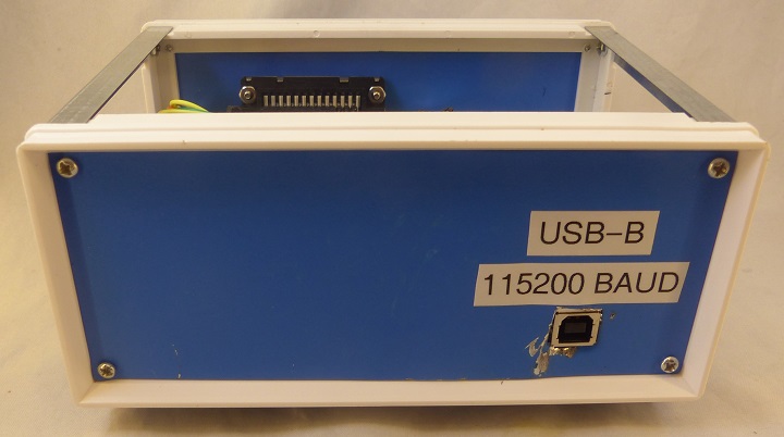
Rear View
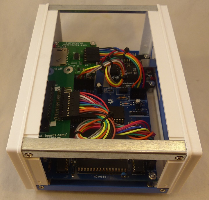
Side/Top View
Connectors
- Triangle/arrow points to pin 1
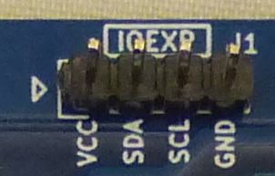
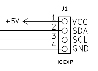
J1 - I2C Expansion
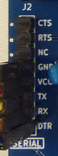
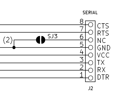
J2 - Serial
- Connects to FTDI-49MM card
- Card does not have DTR line - used for serial download
- RTS-CTS not currently implemented in the IOS firmware
- Did wire to FTDI-49MM card in case it gets added in the future
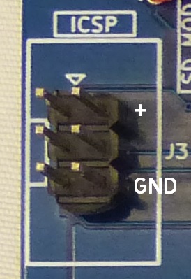
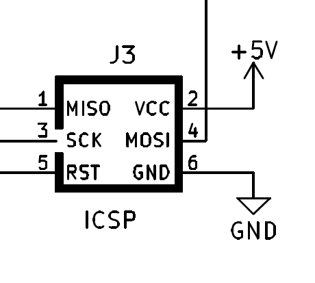
J3 - ICSP
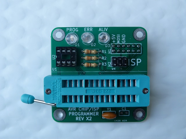
- Temporarily connected to ISP connector on ATProgHead for programming using Arduino as ISP connector and 2x3 jumper
- Used to power front panel LED (resistor on SWLEDX8 card)
- 2x3 to 1x2 Dupont cable
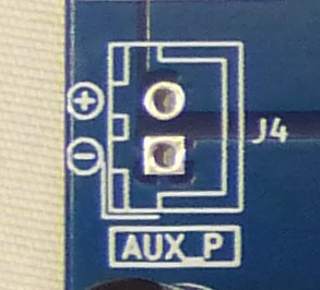
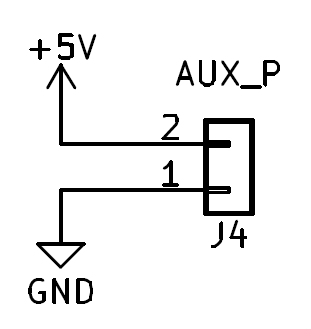
- Power (+5V) and ground pins (would be nice if silkscreen had +, - marked)
J4 - AUX PWR
- Unused/not installed in my build
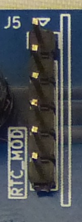
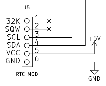
J5 - RTC
- Pin 1 arrow nearest edge of PCB
- 4 pin Dupont cable (Pwr/Gnd/SDA/SCL)
- 2 of 6-pin (1x6) Dupont housting
- Uses pins 3-6 on both ends
- 2 of 6-pin (1x6) Dupont housting
- Wrap RTC in electrical tape to prevent accidental shorting
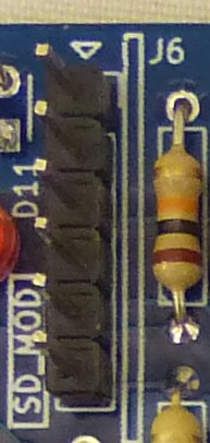
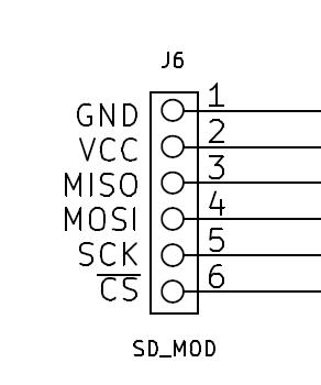
J6 - SD Card
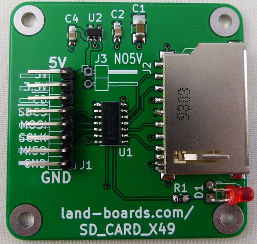
- Connects to SD_CARD_X49 with 6, 8 pin connectors
- Clip out R20 to use LED on SD_CARD_X49
- SD_CARD_X49 set for 5V Host operation
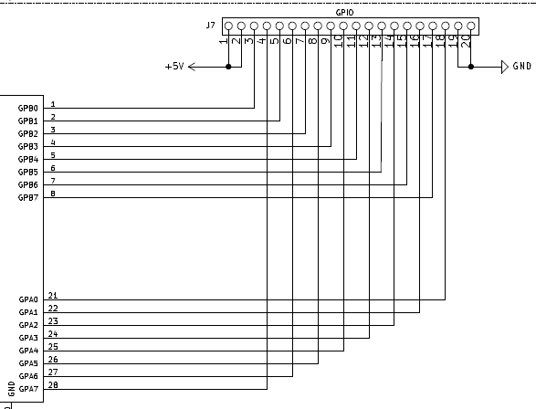
J7 - GPIO
- Demo software in Disk Set 1, Drive A:, File: gpeled.bas
DB-25 connector
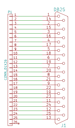
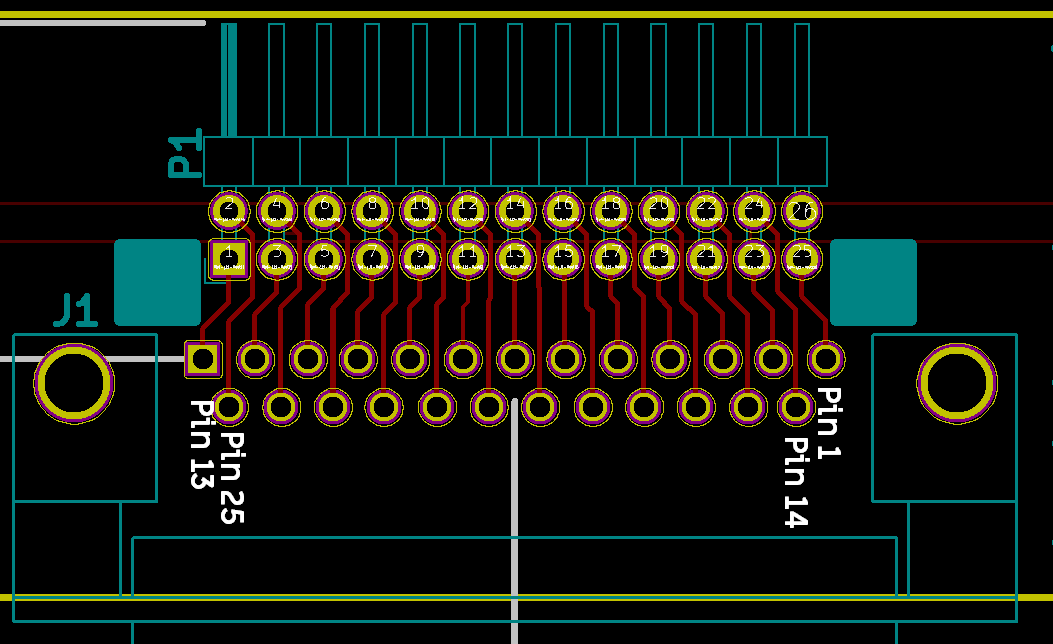
- Connect to DB25RIBBON card
- Use female DB-25 since power is exposed
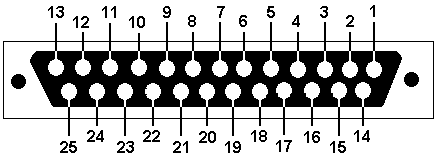
- Wiring shown for male DB-25 connector
Z80-MBC2 to DB25RIBBON Card Wiring
| Port | J7 Pin | DB-25F Pin | P1 Pin | Color | Port | J7 Pin | DB-25F Pin | P1 Pin |
|---|---|---|---|---|---|---|---|---|
| GND | 20 | 1 | 25 | Black | GND | 19 | 14 | 24 |
| GPA0 | 18 | 2 | 23 | Brown | GPB0 | 3 | 15 | 22 |
| GPA1 | 16 | 3 | 21 | Orange | GPB1 | 5 | 16 | 20 |
| GPA2 | 14 | 4 | 19 | Yellow | GPB2 | 7 | 17 | 18 |
| GPA3 | 12 | 5 | 17 | Green | GPB3 | 9 | 18 | 16 |
| GPA4 | 10 | 6 | 15 | Blue | GPB4 | 11 | 19 | 14 |
| GPA5 | 8 | 7 | 13 | Violet | GPB5 | 13 | 20 | 12 |
| GPA6 | 6 | 8 | 11 | Grey | GPB6 | 15 | 21 | 10 |
| GPA7 | 4 | 9 | 9 | White | GPB7 | 17 | 22 | 8 |
| +5V | 2 | 10 | 7 | Red | +5V | 1 | 23 | 6 |
Switches
- Switching between IOS options requires access to Reset and User buttons
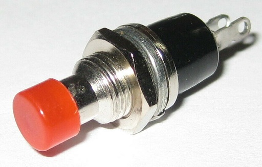
- Pushbutton switches for Reset and User added to Front Panel below SD card mounting
- Reset pushbutton switch is Blue (red would be better but my only red switch was Normally Closed switch)
- User pushbutton switch is Black
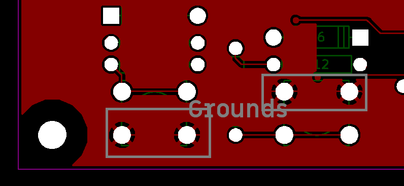
- Soldered wires directly to pushbutton switches on the Z80-MBC2 card
- Used Gerbers to find ground pins
- Chained grounds on switches
LEDs
- Diffused LEDs are better than clear LEDs
- Using 5mm LEDs
- SWLEDX8 - LEDs mounted to front panel through this card
- Removed LEDs from SBC-MBC2 and added 2 pin right angle headers
- Would have been easier if I had planned to have LEDs visible
- Higher resistor values would be better since the LEDs are pretty bright.
- D7 = Blue User LED
- D6 = Green IOS LED
- D5 = Red HALT LED
- D4 = White DMA LED
- D3 = White IOS LED
- D1 = Orange Power LED
- SD card LED is on the FTDI-49MM card
- Removed LEDs from SBC-MBC2 and added 2 pin right angle headers
- D2, D0 LED are not installed
- Resistor installed only for Power LED (Used 1K to reduce the brightness)
- Other LED resistors are on Z80-MBC2 card
- No Switches are installed on card
- Card is sawn off just below switch pins
- Wired to use LED and Switch pins on Header
- Header is mounted on the rear of the card
Programming THE ATMEGA32
- IOS-LITE build (no SD card support)
- Full build with SD card
- Was able to use ATProgHead ICSP 2x3 cable running Arduino as ISP to burn bootloader but not program the code
- Could not use any of my FTDI cards for serial programming since they have RTS/CTS but not DTR
- Most programmer setups in Arduino work just fine with RTS since both are usually pulled, but not the MightyCore
- This is speculation as to why but I am able to program Screwduino cards just fine
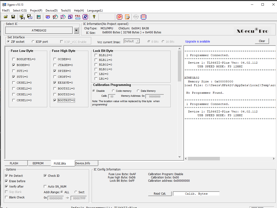
- Used TL866ii to program ATMEGA32 fuses
- The Fuse bits should be: High Byte 0xD6, Low Byte 0xAF, Lock Byte 0xCF.
- Reference: Setting AVR Fuse Bits
- If you use the programmer defaults it sets the clock to 1 MHz which gives a serial port rate of 600 baud (told me I needed to fix the fuses).
- Found path in dump in Arduino IDE:
Arduino: 1.8.13 (Windows 10), Board: "ATmega32, Yes (UART0), EEPROM retained, Standard pinout, BOD 2.7V, LTO disabled, External 16 MHz"
Sketch uses 28642 bytes (88%) of program storage space. Maximum is 32256 bytes.
Global variables use 1213 bytes (59%) of dynamic memory, leaving 835 bytes for local variables. Maximum is 2048 bytes.
C:\Users\HPz420\AppData\Local\Arduino15\packages\arduino\tools\avrdude\6.3.0-arduino18/bin/avrdude -CC:\Users\HPz420\AppData\Local\Arduino15\packages\MightyCore\hardware\avr\2.1.3/avrdude.conf -v -patmega32 -carduino -PCOM23 -b115200 -D -Uflash:w:C:\Users\HPz420\AppData\Local\Temp\arduino_build_883457/S220618_IOS-LITE-Z80-MBC2.ino.hex:i
Software
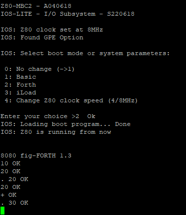
IOS Lite
- IOS Lite does not include SD or RTC support but is useful in checkout
Boot ("Full" IOS)
- Includes SD support
Z80-MBC2 - A040618
IOS - I/O Subsystem - S220718-R240620

IOS: Z80 clock set at 8MHz
IOS: Found GPE Option
IOS: CP/M Autoexec is OFF

IOS: Select boot mode or system parameters:

 0: No change (3)
 1: Basic
 2: Forth
 3: Load OS from Disk Set 0 (CP/M 2.2)
 4: Autoboot
 5: iLoad
 6: Change Z80 clock speed (->4MHz)
 7: Toggle CP/M Autoexec (->ON)
 8: Change Disk Set 0 (CP/M 2.2)

Enter your choice >3  Ok
IOS: Current Disk Set 0 (CP/M 2.2)
IOS: Loading boot program (CPM22.BIN)... Done
IOS: Z80 is running from now


Z80-MBC2 CP/M 2.2 BIOS - S030818-R140319
CP/M 2.2 Copyright 1979 (c) by Digital Research

A>
SD Card (R240620)
- Disk Set 0 (CP/M 2.2)
- Disk Set 1 (QP/M 2.71)
- Disk Set 2 (CP/M 3.0)
- Disk Set 3 (UCSD Pascal)
- Disk Set 4 (Collapse OS)
Disk Set 0 (CP/M 2.2)
F>a:stat
A: R/W, Space: 7908k - CP/M 2.2
B: R/W, Space: 8068k - Turbo Pascal Compiler v3.01A
C: R/W, Space: 7664k - HI-TECH Z80 CP/M C compiler V3.09
D: R/W, Space: 8004k - Microsoft Fortran-80 Compiler v.3.44
E: R/W, Space: 7896k - Microsoft Basic-80 Compiler v.5.30a
F: R/W, Space: 8176k
G: R/W, Space: 8176k
H: R/W, Space: 8176k
I: R/W, Space: 8176k
J: R/W, Space: 8176k
K: R/W, Space: 8176k
L: R/W, Space: 8176k
M: R/W, Space: 8176k
N: R/W, Space: 8176k
O: R/W, Space: 8176k
P: R/W, Space: 8176k

Z80-MBC2 CP/M 2.2 BIOS - S030818-R140319
CP/M 2.2 Copyright 1979 (c) by Digital Research

A>DIR
A: ASCIART  BAS : ASM      COM : AUTOEXEC SUB : AUTOEXEC TXT
A: D        COM : DDT      COM : DUMP     COM : ED       COM
A: GENHEX   COM : GPELED   BAS : GPIO     BAS : HELLO    ASM
A: HELLO    COM : LOAD     COM : MAC      COM : MBASIC   COM
A: MBASIC85 COM : PEG      COM : PIP      COM : RTC      BAS
A: STARTREK BAS : STAT     COM : SUBMIT   COM : TREKINST BAS
A: USERLED  BAS : XMODEM   CFG : XMODEM   COM : XSUB     COM
A: ZDE16    COM : ZDENST16 COM

B>DIR
B: TINST    COM : TURBO    COM : ART      TXT : TINST    DTA
B: TINST    MSG : TURBO    MSG : TURBO    OVR : TURBOMSG OVR
B: SA       PAS : README   TXT

C>DIR
C: $EXEC    COM : ASSERT   H   : C        COM : CGEN     COM
C: CONIO    H   : CPM      H   : CPP      COM : CREF     COM
C: CRTCPM   OBJ : CTYPE    H   : DEBUG    COM : DEHUFF   COM
C: EXEC     H   : FLOAT    H   : HITECH   H   : LIBC     LIB
C: LIBF     LIB : LIBR     COM : LIMITS   H   : LINK     COM
C: MATH     H   : OBJTOHEX COM : OPTIM    COM : OPTIONS
C: P1       COM : README   TXT : RRTCPM   OBJ : SETJMP   H
C: SIGNAL   H   : STAT     H   : STDARG   H   : STDDEF   H
C: STDIO    H   : STDLIB   H   : STRING   H   : SYS      H
C: TIME     H   : UNIXIO   H   : ZAS      COM

D>dir
D: CPMIO    MAC : CRCKLIST CRC : CREF80   COM : DSKDRV   MAC
D: DTBF     MAC : F80      COM : FCHAIN   MAC : FORLIB   REL
D: INIT     MAC : IOINIT   MAC : L80      COM : LIB      COM
D: LPTDRV   MAC : LUNTB    MAC : M80      COM : TTYDRV   MAC
D: README   TXT

E>dir
E: BASCOM   COM : BASCOM   HLP : BASCOM2  HLP : BASLIB   REL
E: BCLOAD       : BRUN     COM : CREF     COM : CREF80   COM
E: README   TXT : L80      COM : LIB80    COM : M80      COM
E: MBASIC   COM : OBSLIB   REL : RANTEST  ASC : RANTEST  BAS
E: RANTEST  COM : RANTEST  REL : SAMPLE   BAS : SAMPLE   COM
E: SAMPLE   REL
Disk Set 1 (QP/M 2.71)
IOS: Current Disk Set 1 (QP/M 2.71)
IOS: Loading boot program (QPMLDR.BIN)... Done
IOS: Z80 is running from now

Z80-MBC2 QP/M 2.71 Cold Loader - S160918
Loading... done

Z80-MBC2 QP/M 2.71 BIOS - S150918
QP/M 2.71 Copyright 1985 (c) by MICROCode Consulting

A>dir
AUTOEXEC.QSB : D       .COM : DHORIZ  .COM : HELLO   .QPM
QBACKUP .COM : QINSTALL.COM : QPATCH  .COM : QPIP    .COM
QPMCLK  .MAC : QPMCMDS .TXT : QPMUTILS.TXT : QSTAMP  .COM
QSTAMPV .COM : QSTAMPX .COM : QSTAT   .COM : QSUB    .COM
QSWEEP  .COM : AUTOEXEC.TXT : TDCNFG  .COM : ZDE16   .COM
ZDENST16.COM : SYSGENQ .COM : ASCIART .BAS : ASM     .COM
DDT     .COM : DUMP    .COM : GENHEX  .COM : GPELED  .BAS
GPIO    .BAS : HELLO   .ASM : HELLO   .COM : LOAD    .COM
MAC     .COM : MBASIC  .COM : PEG     .COM : RTC     .BAS
STARTREK.BAS : TREKINST.BAS : USERLED .BAS : MBASIC85.COM
SETDATE .QSB

A>b:
B>dir
TINST   .COM : TURBO   .COM : ART     .TXT : TINST   .DTA
TINST   .MSG : TURBO   .MSG : TURBO   .OVR : TURBOMSG.OVR
SA      .PAS : README  .TXT : D       .COM

C>dir
$EXEC   .COM : ASSERT  .H   : C       .COM : CGEN    .COM
CONIO   .H   : CPM     .H   : CPP     .COM : CREF    .COM
CRTCPM  .OBJ : CTYPE   .H   : DEBUG   .COM : DEHUFF  .COM
EXEC    .H   : FLOAT   .H   : HITECH  .H   : LIBC    .LIB
LIBF    .LIB : LIBR    .COM : LIMITS  .H   : LINK    .COM
MATH    .H   : OBJTOHEX.COM : OPTIM   .COM : OPTIONS .
P1      .COM : README  .TXT : RRTCPM  .OBJ : SETJMP  .H
SIGNAL  .H   : STAT    .H   : STDARG  .H   : STDDEF  .H
STDIO   .H   : STDLIB  .H   : STRING  .H   : SYS     .H
TIME    .H   : UNIXIO  .H   : ZAS     .COM : D       .COM

D>dir
CPMIO   .MAC : CRCKLIST.CRC : CREF80  .COM : DSKDRV  .MAC
DTBF    .MAC : F80     .COM : FCHAIN  .MAC : FORLIB  .REL
INIT    .MAC : IOINIT  .MAC : L80     .COM : LIB     .COM
LPTDRV  .MAC : LUNTB   .MAC : M80     .COM : TTYDRV  .MAC
README  .TXT : D       .COM

E>dir
BASCOM  .COM : BASCOM  .HLP : BASCOM2 .HLP : BASLIB  .REL
BCLOAD  .    : BRUN    .COM : CREF    .COM : CREF80  .COM
README  .TXT : L80     .COM : LIB80   .COM : M80     .COM
MBASIC  .COM : OBSLIB  .REL : RANTEST .ASC : RANTEST .BAS
RANTEST .COM : RANTEST .REL : SAMPLE  .BAS : SAMPLE  .COM
SAMPLE  .REL : D       .COM
Disk Set 2 (CP/M 3.0)
>Disk Set 2 (CP/M 3.0)

IOS: Current Disk Set 2 (CP/M 3.0)
IOS: Loading boot program (CPMLDR.COM)... Done
IOS: Z80 is running from now

Z80-MBC2 CPMLDR BIOS - S180918

CP/M V3.0 Loader
Copyright (C) 1982, Digital Research

 BNKBIOS3 SPR  F600  0600
 BNKBIOS3 SPR  5300  2D00
 RESBDOS3 SPR  F000  0600
 BNKBDOS3 SPR  2500  2E00

 60K TPA

Z80-MBC2 128KB (Banked) CP/M V3.0
Z80-MBC2 BIOS Modules: S200918, S210918-R170319, S220918-R180319, S290918,
 S170319

A>dir
A: ASCIART  BAS : AUTOEXEC COM : AUTOEXEC TXT : BDOS3    SPR : BNKBDOS3 SPR
A: CCP      COM : COPYSYS  COM : CPM3     SYS : CPM3-128 SYS : CPM3-64  SYS
A: CPMLDR   COM : CPMLDR   REL : CPM-Y2K  TXT : CRCK     COM : DATE     COM
A: DEVICE   COM : DIR      COM : DUMP     COM : ED       COM : ERASE    COM
A: GENCOM   COM : GENCPM   COM : GENHEX   COM : GET      COM : GPELED   BAS
A: GPIO     BAS : HELLO    ASM : HELLO    COM : HELP     COM : HELP     HLP
A: HEXCOM   COM : INITDIR  COM : LIB      COM : LINK     COM : LOAD     COM
A: MAC      COM : MBASIC   COM : MBASIC85 COM : PATCH    COM : PEG      COM
A: PIP      COM : PROFILE  SU  : PUT      COM : README   1ST : RENAME   COM
A: RESBDOS3 SPR : RMAC     COM : RTC      BAS : SAVE     COM : SET      COM
A: SETDEF   COM : SHOW     COM : SID      COM : STARTREK BAS : SUBMIT   COM
A: SYS128   SUB : SYS64    SUB : TREKINST BAS : TYPE     COM : USERLED  BAS
A: XMODEM   CFG : XMODEM   COM : XREF     COM : ZDE16    COM : ZDENST16 COM
A: ZSID     COM : CATCHUM  COM : CATCHUM  DAT : CATCONF  COM : GORILLA  COM
A: LADCONF  COM : LADDER   COM : LADDER   DAT

B>dir
B: ART      TXT : SA       PAS : TINST    COM : TINST    DTA : TINST    MSG
B: TURBO    COM : TURBO    MSG : TURBO    OVR : TURBOMSG OVR : USERLED  PAS

C>dir
C: $EXEC    COM : ASSERT   H   : C        COM : CGEN     COM : CONIO    H
C: CPM      H   : CPP      COM : CREF     COM : CRTCPM   OBJ : CTYPE    H
C: DEBUG    COM : DEHUFF   COM : EXEC     H   : FLOAT    H   : HITECH   H
C: LIBC     LIB : LIBF     LIB : LIBR     COM : LIMITS   H   : LINK     COM
C: MATH     H   : OBJTOHEX COM : OPTIM    COM : P1       COM : README   TXT
C: RRTCPM   OBJ : SETJMP   H   : SIGNAL   H   : STAT     H   : STDARG   H
C: STDDEF   H   : STDIO    H   : STDLIB   H   : STRING   H   : SYS      H
C: TIME     H   : UNIXIO   H   : ZAS      COM

D>dir
D: CPMIO    MAC : CRCKLIST CRC : CREF80   COM : DSKDRV   MAC : DTBF     MAC
D: F80      COM : FCHAIN   MAC : FORLIB   REL : INIT     MAC : IOINIT   MAC
D: L80      COM : LIB      COM : LPTDRV   MAC : LUNTB    MAC : M80      COM
D: README   TXT : TTYDRV   MAC

E>dir
E: INSTALL  COM : MAILMRGE OVR : MERGPRIN OVR : WIMSGS   OVR : WS       COM
E: WS       OVR : WSCHANGE COM : WSCHANGE OVR : WSCHHELP OVR : WSHELP   OVR
E: WSMSGS   OVR : WSOVLY1  OVR : WSPRINT  OVR : WSSHORT  OVR : WSU      COM
ADD FILES USING CPMTOOLSGUI
- The Z80-MBC2 maps any disk like A: B: C: etc. into an image file on SD card with this file name: DSxNyy.DSK;
- where x (from 0 to 9) is OS:
- 0 = CP/M 2.2
- 1 = QP/M 2.71
- 2 = CP/M 3
- and yy (from 00 to 15) is the disk (00 = A: 01 = B: etc.).
- where x (from 0 to 9) is OS:
- You can download CpmtoolsGUI (English Windows version) from here.
- Extract the file CpmtoolsGUI.exe in a new folder and add/overwrite the file diskdefs copying it from the folder cpmtools inside the SD.
STEP 1
- Select in the upper left window (Image File) of the CpmtoolsGUI tool the virtual disk where you want to add files.
- For CP/M 2.2 and QP/M 2.71: select "z80mbc2-d0" only for disk 0 or "z80mbc2-d1" for the others (disk 1 - 15) in the bottom left window (Format) of CpmtoolsGUI.
- In the following image is selected (Image File) the disk DS0N02.DSK that corresponds to the disk C: (yy = disk = 02) of the CP/M 2.2 OS (x = 0):
- In the center window you can see all the files inside the selected virtual disk (disk 0 - 15).
- Please note that if you choose an empty disk (like P:) you won't see any file name in the center window of the CpmtoolsGUI tool.
- In the following image is selected (Image File) the disk DS0N02.DSK that corresponds to the disk C: (yy = disk = 02) of the CP/M 2.2 OS (x = 0):
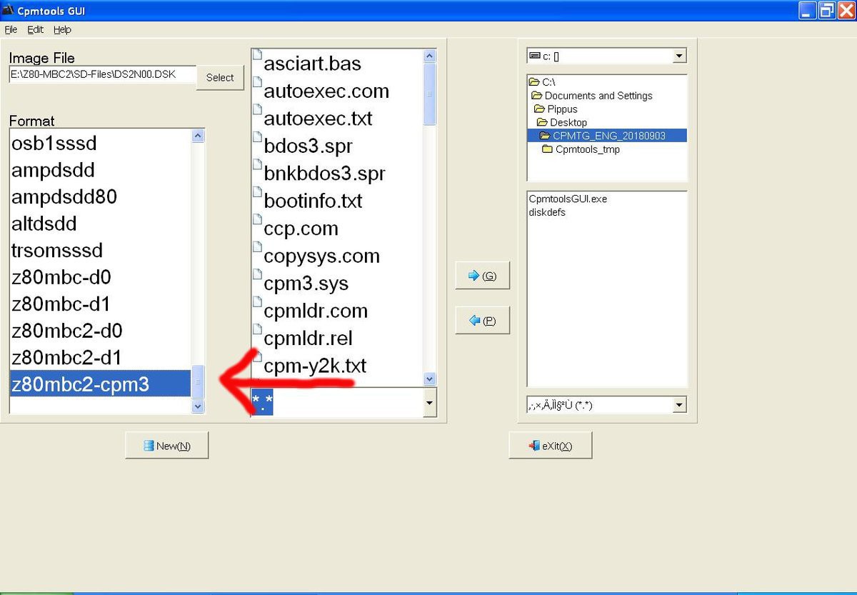
- For CP/M 3: select in the bottom left window (Format) of CpmtoolsGUI "z80mbc2-cpm3" for any disk.
- In the following image is selected (Image File) the disk DS2N00.DSK that corresponds to the disk A: (yy = disk = 00) of the CP/M 3 OS (x = 2):
- For CP/M 2.2 and QP/M 2.71: select "z80mbc2-d0" only for disk 0 or "z80mbc2-d1" for the others (disk 1 - 15) in the bottom left window (Format) of CpmtoolsGUI.
STEP 2
- To add one or more files to the selected virtual disk you have simply point the upper right selection window to the folder where the new files are stored in your PC, select them using the bottom right selection window and press the "<- P" button.
- After the add you'll see the added file names in the center window (together with the others file previously present).
STEP 3
- Exit from the the CpmtoolsGUI tool pressing the eXit button.
I/O Programming
- User Pushbutton
- User LED
- 16-bit GPIO
- GPIO is via MCP23017 - Datasheet
- Real-Time Clock
User LED and Pushbutton
userled.bas
01 REM ****************************************
02 REM
03 REM Z80-MBC2 USER led blink demo:
04 REM
05 REM Blink USER led until USER key is pressed
06 REM
07 REM ****************************************
08 REM
13 PRINT "Press USER key to exit"
14 LEDUSER = 0 : REM USER LED write Opcode (0x00)
15 KEYUSER = 128 : REM USER KEY read Opcode (0x80)
16 PRINT "Now blinking..."
18 OUT 1,LEDUSER : REM Write the USER LED write Opcode
20 OUT 0,1 : REM Turn USER LED on
30 GOSUB 505 : REM Delay sub
40 OUT 1,LEDUSER : REM Write the USER LED write Opcode
45 OUT 0,0 : REM Turn USER LED off
50 GOSUB 505 : REM Delay
60 GOTO 18
490 REM
500 REM * * * * * DELAY SUB
501 REM
505 FOR J=0 TO 150
506 OUT 1,KEYUSER : REM Write the USER KEY read Opcode
507 IF INP(0)=1 THEN GOTO 700 : REM Exit if USER key is pressed
510 NEXT J
520 RETURN
690 REM
691 REM * * * * * PROGRAM END
692 REM
700 OUT 1,LEDUSER : REM Write the USER LED write Opcode
710 OUT 0,0 : REM Turn USER LED off
720 PRINT "Terminated by USER Key"
GPIO
gpio.bas
1 REM * * * GPIO EXPANSION MODULE (A080117) DEMO  * * *
2 REM
3 REM (USER Key -> slow led, GPIO-A(9) Key -> fast led)
4 REM --------------------------------------------------
5 REM Demo HW wiring (see A080117 schematic):
6 REM
7 REM   GPIO-B
8 REM    (J3)
9 REM   +----+   LED
10 REM  | 2  |--->|---+
11 REM  | 3  |--->|---+      RESISTOR
12 REM  | 4  |--->|---+        680
13 REM  | 5  |--->|---+-------/\/\/-----o GND
14 REM  | 6  |--->|---+
15 REM  | 7  |--->|---+
16 REM  | 8  |--->|---+
17 REM  | 9  |--->|---+
18 REM  +----+        |
19 REM                |
20 REM                |
21 REM  GPIO-A        |
22 REM   (J4)         |
23 REM  +----+   LED  |
24 REM  | 2  |--->|---+
25 REM  | 3  |--->|---+
26 REM  | 4  |x
27 REM  | 5  |x
28 REM  | 6  |x
29 REM  | 7  |x     PUSH BUTTON            RESISTOR
30 REM  | 8  |x        ---                   1K
31 REM  | 9  |---------o o------------------/\/\/-----o GND
32 REM  +----+
33 REM
34 REM
35 REM
36 REM --------------------------------------------------
37 REM
38 REM Set MCP23017 GPIOB all pins as output (IODIRB=0x00)
39 OUT 6, 0
40 REM Set MCP23017 GPIOA 0-1 as output, others as input (IODIRA=0xFC)
41 OUT 5, 252
42 REM Set MCP23017 GPIOA 2-7 pull-up resistor on (GPPUA=0xFC)
43 OUT 7, 252
45 REM Left Shift user funcion definition
50 DEF FNLSH(X)=((X*2) AND 255)
55 REM Init GPIO output ports
60 OUT 3, 0 : REM Clear MCP23017 GPIOA port
62 OUT 4, 0 : REM Clear MCP23017 GPIOB port
64 GOSUB 700 : REM Set slow shift
68 REM Main
70 A=1
80 FOR I=0 TO 7
90 OUT 4, A : REM Write to MCP23017 GPIOB port
100 GOSUB 500
110 A=FNLSH(A)
120 NEXT I
130 OUT 4, 0 : REM Clear MCP23017 GPIOB port
135 A=1
140 FOR I=0 TO 1
150 OUT 3, A : REM Write to MCP23017 GPIOA port
160 GOSUB 500
170 A=FNLSH(A)
190 NEXT I
200 OUT 3, 0 : REM Clear MCP23017 GPIOA port
210 GOTO 70 : REM Play it again, Sam...
220 REM
500 REM * * * * * DELAY SUB
505 FOR J=0 TO K
507 IF INP(0)=1 THEN GOSUB 700 : REM Read USER key
508 IF (INP(3) AND 128)=0 THEN GOSUB 600 : REM Read MCP23017 GPIOA 7 key
510 NEXT J
520 RETURN
530 REM
600 REM * * * * * SET FAST SHIFT SUB
610 K=1
620 OUT 0, 1 : REM USER led ON
630 RETURN
640 REM
700 REM * * * * * SET SLOW SHIFT SUB
710 K=30
720 OUT 0, 0 : REM USER led OFF
730 RETURN
Real-Time Clock
- Write 1 to Port 132
- Read 0 repeatedly
- SEC
- MINUTES
- HOURS
- DAY
- MONTH
- YEAR
- TEMP
rtc.bas
15 OUT 1,132 : REM Write the DATETIME read Opcode
20 SEC = INP(0) : REM Read a RTC parameter
30 MINUTES = INP(0) : REM Read a RTC parameter
40 HOURS = INP(0) : REM Read a RTC parameter
50 DAY = INP(0) : REM Read a RTC parameter
60 MNTH = INP(0) : REM Read a RTC parameter
70 YEAR = INP(0) : REM Read a RTC parameter
80 TEMP = INP(0) : REM Read a RTC parameter
83 IF TEMP < 128 THEN 90 : REM Two complement correction
85 TEMP = TEMP - 256
90 PRINT
100 PRINT "THE TIME IS: ";
110 PRINT HOURS; : PRINT ":"; : PRINT MINUTES; : PRINT ":"; : PRINT SEC
120 PRINT "THE DATE IS: ";
125 YEAR= YEAR+ 2000
130 PRINT DAY; : PRINT "/"; : PRINT MNTH; : PRINT "/"; : PRINT YEAR
135 PRINT "THE TEMPERATURE IS: ";
140 PRINT TEMP; : PRINT "C"
145 PRINT
Videos
