Difference between revisions of "ER-PROTO-02"
Jump to navigation
Jump to search
Blwikiadmin (talk | contribs) |
Blwikiadmin (talk | contribs) |
||
| (47 intermediate revisions by the same user not shown) | |||
| Line 1: | Line 1: | ||
| + | [[File:tindie-mediums.png|link=https://www.tindie.com/products/28896/]] | ||
| + | |||
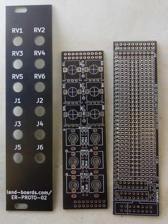
[[file:ER-PROTO-02_SET_P1080833-720pxV.jpg]] | [[file:ER-PROTO-02_SET_P1080833-720pxV.jpg]] | ||
== Features == | == Features == | ||
| − | * Eurorack Prototyping card set | + | * Eurorack Prototyping 3 card set |
| + | ** Front panel card | ||
| + | ** Controls | ||
| + | ** Prototyping daughtercard | ||
* 6 HP wide (30mm) front panel | * 6 HP wide (30mm) front panel | ||
| + | * Controls and prototyping cards are 28mm wide | ||
* 3U tall | * 3U tall | ||
| + | * Pots on top, jacks on bottom | ||
| + | ** Easier to adjust pots without bumping into pots | ||
| + | ** Pots are more often accessed than jacks | ||
* 0-6 POTS | * 0-6 POTS | ||
| − | ** Series resistors on pot wiper | + | ** Series resistors on pot wiper on controls card |
** All 3 pot pins brought to top header | ** All 3 pot pins brought to top header | ||
| − | * 0-6 Jacks | + | ** Jumpers on control card allow GND/VCC to be set on pot ends |
| − | * Tip/ring brought to header near bottom | + | * 0-6 "Thinkicon style" Jacks |
| − | + | ** Can use stereo or mono jacks | |
| − | + | ** Tip/ring brought to header near bottom | |
| − | |||
* Large prototyping area | * Large prototyping area | ||
| − | * | + | * Power/GND down center of card |
* Bussed connections horizontally | * Bussed connections horizontally | ||
| − | * Front Panel | + | * Front Panel has generic labels |
** Cover with White on Black P-Touch labels | ** Cover with White on Black P-Touch labels | ||
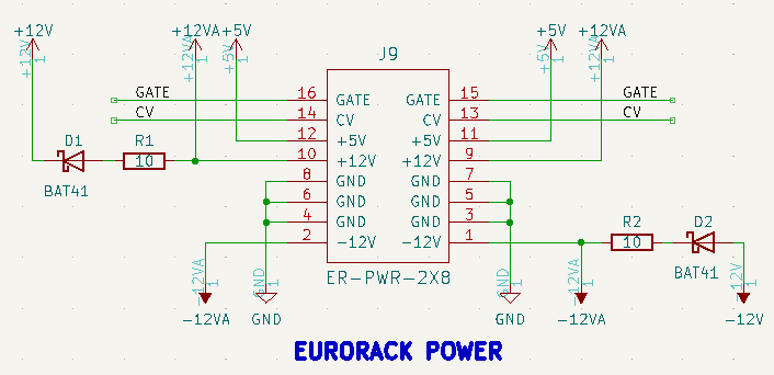
| + | * Eurorack power connector - can use either 2x5 or 2x8 IDC box connector | ||
| + | ** Series resistors/protection diodes on +12/-12V connections | ||
=== Daughtercard Prototyping Area === | === Daughtercard Prototyping Area === | ||
| + | |||
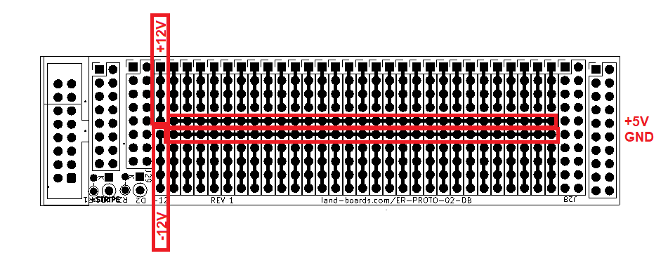
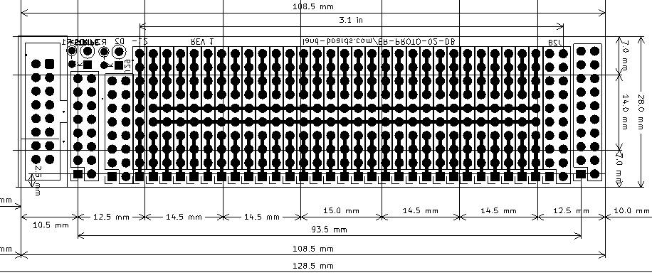
| + | * +5V connections are directly connected to +5V pins on IDC connector if 16 pin IDC connector is used | ||
| + | * If a 10 pin IDC connector is used the +5V connections are no connected to the Eurorack power | ||
| + | * This is used with an [[Arduino Nano]] or [[Arduino Pro Mini]], RAW power can be fed from the +12V and the +5V gets connected to the Arduino module | ||
[[FILE:ER-PROTO-02-DB_REAR_PWR.png]] | [[FILE:ER-PROTO-02-DB_REAR_PWR.png]] | ||
| + | |||
| + | ==== Optional 5V regulator on card ==== | ||
| + | |||
| + | * Can also put a regulator on the card | ||
| + | * RA1 is R1 on daughtercard | ||
| + | * R1/D1 are on the card | ||
| + | |||
| + | [[file:ER-DELAY-01_POWER.PNG]] | ||
| + | |||
| + | [[file:ER-PROTO-02_DB_Power5V.PNG]] | ||
| + | |||
| + | == Example Card Stackup == | ||
| + | |||
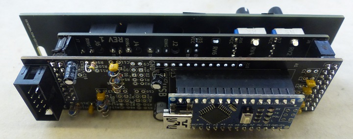
| + | * Female sockets mounted to rear of controls card | ||
| + | * Male pin headers mounted to "rear" of daughtercard | ||
| + | |||
| + | [[file:ER-BEZIER-CV_P1080844-720px.jpg]] | ||
== Jacks/Headers/Pots == | == Jacks/Headers/Pots == | ||
| Line 78: | Line 109: | ||
* Can install 2x8 or 2x5 IDC box header | * Can install 2x8 or 2x5 IDC box header | ||
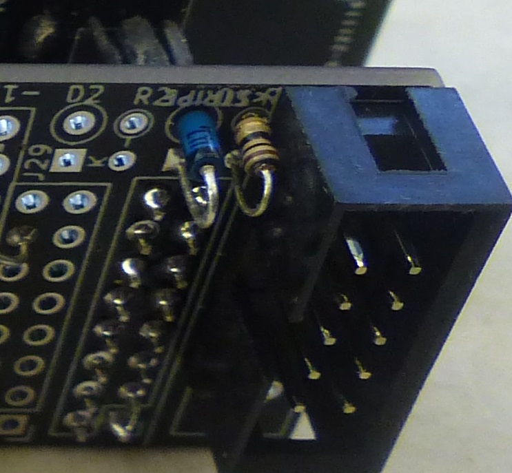
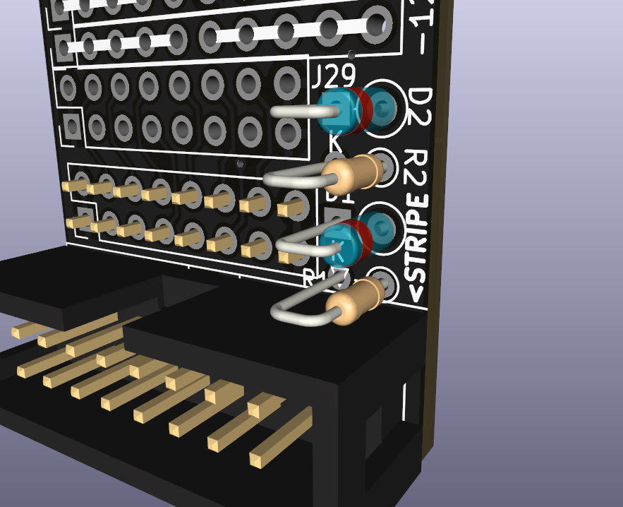
| + | * D1/R1 Diode/resistor for +12V power | ||
| + | ** Shown with 2x5 box header | ||
| + | |||
| + | [[file:ER-SCOPE-01 P1080978-POWER.jpg]] | ||
| + | |||
| + | == Schematics == | ||
| + | |||
| + | * [http://land-boards.com/ER-PROTO-02/ER-PROTO-02-CTLS_Rev1_Schematic.pdf ER-PROTO-02-CTLS Rev 1 Schematic] | ||
| + | * [http://land-boards.com/ER-PROTO-02/ER-PROTO-02-DB_Rev1_Schematic.pdf ER-PROTO-02-DB Rev1 Schematic] | ||
== Mechanicals == | == Mechanicals == | ||
| Line 85: | Line 125: | ||
== Examples == | == Examples == | ||
| − | * [[ER-MOZZI-DB]] | + | Cards built on the PROTO-02 card set |
| − | * [[ | + | |
| − | * [[CV SHIFT on ER-PROTO-02]] | + | === ER-BEZIER-CV === |
| − | * [[ER-USB-MIDI | + | |
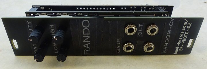
| − | + | [[file:RANDO_P1080937-720px.jpg]] | |
| − | * [[ER- | + | |
| − | * [[ER- | + | * [[ER-BEZIER-CV]] - Random Control Voltages (CVs) |
| + | |||
| + | === ER-CV-AMP3 === | ||
| + | |||
| + | [[file:ER-PROTO-02-CV_AMP_P1080931-720px.jpg]] | ||
| + | |||
| + | * [[ER-CV-AMP3]] - Amplify CVs or GATES by 2 | ||
| + | |||
| + | === ER-DELAY-01 === | ||
| + | |||
| + | [[file:ER-DELAY-01_P1090072-720px.jpg]] | ||
| + | |||
| + | * [[ER-DELAY-01]] - Echo | ||
| + | |||
| + | === ER-GATE-SEQ-01 === | ||
| + | |||
| + | [[file:ER-GATE-SEQ-01_P1080960-720px.jpg]] | ||
| + | |||
| + | * [[ER-GATE-SEQ-01]] - GATE Sequencer | ||
| + | |||
| + | === ER-LEDS === | ||
| + | |||
| + | [[file:ER-LEDS_P1080999-720px.jpg]] | ||
| + | |||
| + | * [[ER-LEDS]] - Control a NeoPixel strip | ||
| + | |||
| + | === ER-MOZZI-DB === | ||
| + | |||
| + | [[file:ER-PROTO-02-MOZZI-DB_P1080850-720PX.jpg]] | ||
| + | |||
| + | * [[ER-MOZZI-DB]] - VCOs based on MOZZI | ||
| + | |||
| + | === ER-MOZZI-DB-03 === | ||
| + | |||
| + | * [[ER-MOZZI-DB-03]] - Flexible MOZZI | ||
| + | |||
| + | === ER-MOZZI-DRUMS === | ||
| + | |||
| + | [[file:ER-MOZZI-DRUMS_P1090041-F_B_720PX.jpg]] | ||
| + | |||
| + | * [[ER-MOZZI-DRUMS]] - Drums module | ||
| + | |||
| + | === ER-SCOPE-01 === | ||
| + | |||
| + | [[file:ER-SCOPE-01_P1090046-720px.jpg]] | ||
| + | |||
| + | * [[ER-SCOPE-01]] - Scope | ||
| + | |||
| + | === ER-SH-02 === | ||
| + | |||
| + | [[file:ER-PROTO-02_S-H_P1090119-720px.jpg]] | ||
| + | |||
| + | * [[ER-SH-02]] | ||
| + | |||
| + | === CV SHIFT on ER-PROTO-02 === | ||
| + | |||
| + | * [[CV SHIFT on ER-PROTO-02]] | ||
| + | |||
| + | === ER-STIX === | ||
| + | |||
| + | [[file:ER-STIX_P1080921_720PX.jpg]] | ||
| + | |||
| + | * [[ER-STIX]] - Mutable Instruments Branches "like" | ||
| + | |||
| + | === ER-USB-MIDI === | ||
| + | |||
| + | [[file:ER-USB-MIDI_P1090014-720PX.jpg]] | ||
| + | |||
| + | * [[ER-USB-MIDI]] - USB MIDI to TRS A | ||
| + | |||
| + | == Issues == | ||
| + | |||
| + | === Rev 2 Control Card === | ||
| + | |||
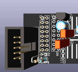
| + | * Clean up silkscreen overlaps near R1, D1, STRIPE | ||
| + | |||
| + | [[file:ER-PROTO-02-DB_pwr.png]] | ||
| + | |||
| + | |||
| + | === Rev 1 === | ||
| + | |||
| + | * No Issues notes | ||
== Assembly Sheet == | == Assembly Sheet == | ||
* [[ER-PROTO-02 Rev 1 Assembly Sheet]] | * [[ER-PROTO-02 Rev 1 Assembly Sheet]] | ||
Latest revision as of 14:15, 10 March 2023
Contents
Features
- Eurorack Prototyping 3 card set
- Front panel card
- Controls
- Prototyping daughtercard
- 6 HP wide (30mm) front panel
- Controls and prototyping cards are 28mm wide
- 3U tall
- Pots on top, jacks on bottom
- Easier to adjust pots without bumping into pots
- Pots are more often accessed than jacks
- 0-6 POTS
- Series resistors on pot wiper on controls card
- All 3 pot pins brought to top header
- Jumpers on control card allow GND/VCC to be set on pot ends
- 0-6 "Thinkicon style" Jacks
- Can use stereo or mono jacks
- Tip/ring brought to header near bottom
- Large prototyping area
- Power/GND down center of card
- Bussed connections horizontally
- Front Panel has generic labels
- Cover with White on Black P-Touch labels
- Eurorack power connector - can use either 2x5 or 2x8 IDC box connector
- Series resistors/protection diodes on +12/-12V connections
Daughtercard Prototyping Area
- +5V connections are directly connected to +5V pins on IDC connector if 16 pin IDC connector is used
- If a 10 pin IDC connector is used the +5V connections are no connected to the Eurorack power
- This is used with an Arduino Nano or Arduino Pro Mini, RAW power can be fed from the +12V and the +5V gets connected to the Arduino module
Optional 5V regulator on card
- Can also put a regulator on the card
- RA1 is R1 on daughtercard
- R1/D1 are on the card
Example Card Stackup
- Female sockets mounted to rear of controls card
- Male pin headers mounted to "rear" of daughtercard
Jacks/Headers/Pots
Controls Card - Jacks/Headers/Pots
- 0-6 Jacks
- 0-6 Pots
- Headers to connect to Prototyping card
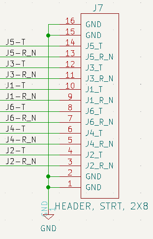
J1-J6 Jacks
- Jacks have resistors on Tip/Ring-Switch
- Typically Tip = 0 Ohm jumper, Ring/Switch = Do Not Populate (DNP on schematic)
- Tip resistors: R7, R9, R11, R13, R15, R17
- Ring/Switch resistors: R8, R10, R12, R14, R16, R18
J7 Header
- 2x8 female header
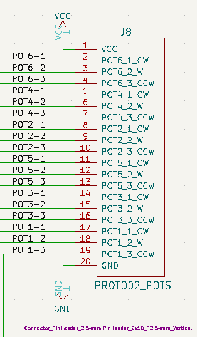
J8 Header
- 2x10 female headers
Pots
- Pots have optional pull-up/pulldown jumper positions
- Install jumpers if pots are used as controls voltages
- Do not install jumpers if pots are used as volume control voltages
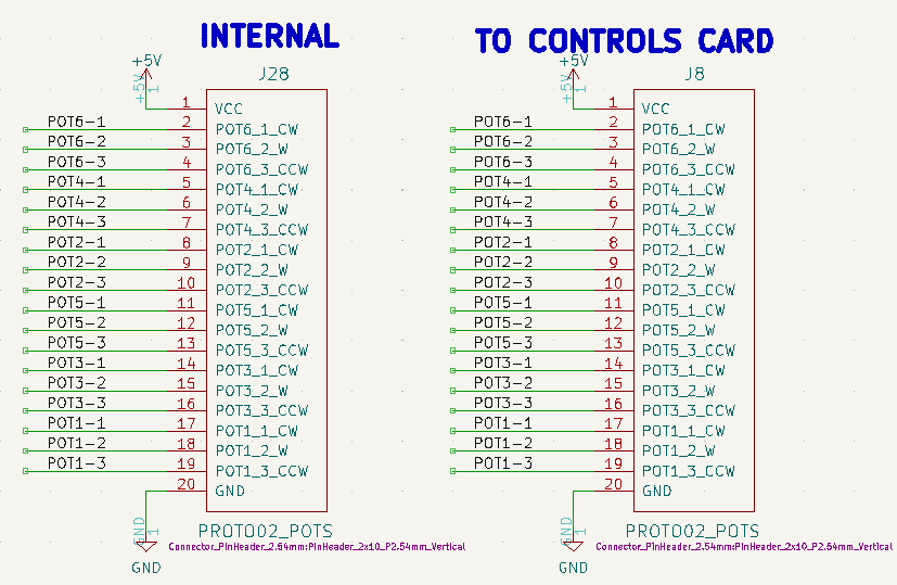
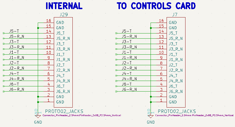
Prototyping Daughtercard
- Controls card connections are typically male headers
J8, J28 - Pot connections
J7, J29 - Jack connections
J9 - Eurorack Power
- Can install 2x8 or 2x5 IDC box header
- D1/R1 Diode/resistor for +12V power
- Shown with 2x5 box header
Schematics
Mechanicals
Examples
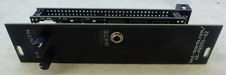
Cards built on the PROTO-02 card set
ER-BEZIER-CV
- ER-BEZIER-CV - Random Control Voltages (CVs)
ER-CV-AMP3
- ER-CV-AMP3 - Amplify CVs or GATES by 2
ER-DELAY-01
- ER-DELAY-01 - Echo
ER-GATE-SEQ-01
- ER-GATE-SEQ-01 - GATE Sequencer
ER-LEDS
- ER-LEDS - Control a NeoPixel strip
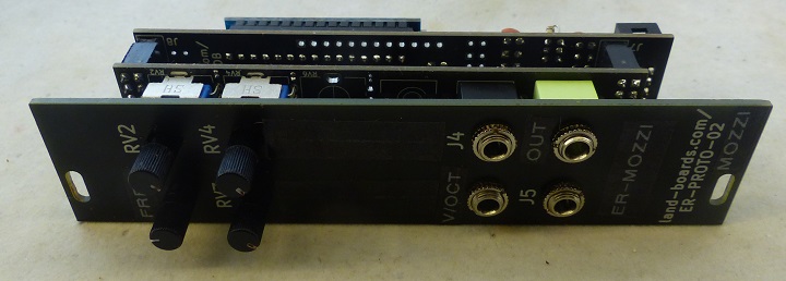
ER-MOZZI-DB
- ER-MOZZI-DB - VCOs based on MOZZI
ER-MOZZI-DB-03
- ER-MOZZI-DB-03 - Flexible MOZZI
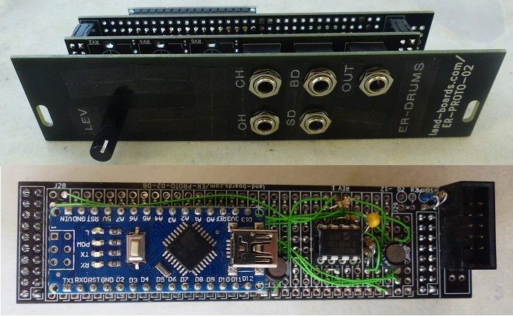
ER-MOZZI-DRUMS
- ER-MOZZI-DRUMS - Drums module
ER-SCOPE-01
- ER-SCOPE-01 - Scope
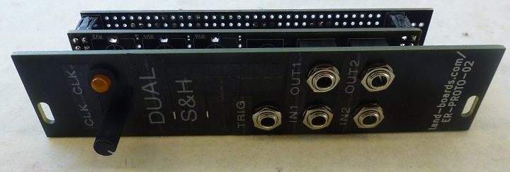
ER-SH-02
CV SHIFT on ER-PROTO-02
ER-STIX
- ER-STIX - Mutable Instruments Branches "like"
ER-USB-MIDI
- ER-USB-MIDI - USB MIDI to TRS A
Issues
Rev 2 Control Card
- Clean up silkscreen overlaps near R1, D1, STRIPE
Rev 1
- No Issues notes

