Difference between revisions of "Arduino Based Test Station"
Jump to navigation
Jump to search
Blwikiadmin (talk | contribs) |
Blwikiadmin (talk | contribs) |
||
| (8 intermediate revisions by the same user not shown) | |||
| Line 147: | Line 147: | ||
* From [https://www.st.com/content/ccc/resource/technical/document/application_note/51/5f/03/1e/bd/9b/45/be/CD00264342.pdf/files/CD00264342.pdf/jcr:content/translations/en.CD00264342.pdf AN3155] | * From [https://www.st.com/content/ccc/resource/technical/document/application_note/51/5f/03/1e/bd/9b/45/be/CD00264342.pdf/files/CD00264342.pdf/jcr:content/translations/en.CD00264342.pdf AN3155] | ||
[[File:SerialPropogramming (AN3155).PNG]] | [[File:SerialPropogramming (AN3155).PNG]] | ||
| + | |||
| + | == Useful Arduino Code == | ||
| + | |||
| + | Here's some useful pieces of Arduino code | ||
| + | |||
| + | === Wait for Host Serial to Connect === | ||
| + | |||
| + | <pre> | ||
| + | Serial.begin(9600); | ||
| + | while (!Serial); // wait for serial port to connect. Needed for native USB | ||
| + | </pre> | ||
| + | |||
| + | === uint8_t checkI2CAddr(uint8_t addr) === | ||
| + | |||
| + | Check if there is an I2C device at an address | ||
| + | |||
| + | <pre> | ||
| + | //////////////////////////////////////////////////////////////////////////// | ||
| + | // uint8_t checkI2CAddr(uint8_t addr) - Check that an I2C device is present | ||
| + | // Pass: addr - I2C address | ||
| + | // Returns: | ||
| + | // 0 : success | ||
| + | // 1 : data too long to fit in transmit buffer | ||
| + | // 2 : received NACK on transmit of address | ||
| + | // 3 : received NACK on transmit of data | ||
| + | // 4 : other error | ||
| + | //////////////////////////////////////////////////////////////////////////// | ||
| + | |||
| + | uint8_t checkI2CAddr(uint8_t addr) | ||
| + | { | ||
| + | Wire.beginTransmission(addr); | ||
| + | return (Wire.endTransmission()); | ||
| + | } | ||
| + | </pre> | ||
| + | |||
| + | === uint8_t checkIfMCP23017(uint8_t addr) === | ||
| + | |||
| + | Check if an I2C device is an MCP23017 at an address | ||
| + | |||
| + | <pre> | ||
| + | //////////////////////////////////////////////////////////////////////////// | ||
| + | // uint8_t checkIfMCP23017(uint8_t addr) | ||
| + | // Check to see if the I2C part is a MCP23017 | ||
| + | // The GPU Pullup A register (internal register address 0x0c) is present | ||
| + | // in a MCP23017 but not in a MCP23008. | ||
| + | // Pass: addr - I2C address | ||
| + | // Returns | ||
| + | // 0 : Not an MCP23017 | ||
| + | // 1 : Likely an MCP23017 | ||
| + | //////////////////////////////////////////////////////////////////////////// | ||
| + | |||
| + | uint8_t checkIfMCP23017(uint8_t addr) | ||
| + | { | ||
| + | // Write 0x55 to MCP23017_GPPUA (0x0c) | ||
| + | Wire.beginTransmission(addr); | ||
| + | Wire.write(0x0c); | ||
| + | Wire.write(0x55); | ||
| + | Wire.endTransmission(1); | ||
| + | // Read back | ||
| + | Wire.beginTransmission(addr); | ||
| + | Wire.write(0x0c); | ||
| + | Wire.endTransmission(); | ||
| + | Wire.requestFrom(addr, 1); | ||
| + | if (Wire.read() == 0x55) | ||
| + | { | ||
| + | Serial.println(F("Detected MCP23017")); | ||
| + | return 1; | ||
| + | } | ||
| + | else | ||
| + | { | ||
| + | Serial.println(F("Detected MCP23008")); | ||
| + | return 0; | ||
| + | } | ||
| + | } | ||
| + | |||
| + | </pre> | ||
== Cards Supported == | == Cards Supported == | ||
| Line 199: | Line 275: | ||
== Cable Sets == | == Cable Sets == | ||
| − | [[ | + | [[FILE:ODTSTSTR_CBLS_P119_720pv.jpg]] |
* Particular cable sets for cards | * Particular cable sets for cards | ||
| + | * Bounce LED and Loopback to Test Station Cables | ||
== Software == | == Software == | ||
Latest revision as of 13:58, 23 March 2022
Contents
Hardware
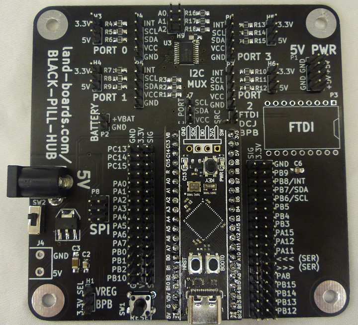
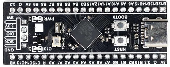
- BLACK-PILL-HUB - Test Station Processing element
- STM32 Black Pill - CPU card
- Preferred choice due to nearly unlimited resources
- Previous CPU choices
- BLUE-PILL-HUB
- FTDI card required
- NANO-BKOUT
- BLUE-PILL-HUB
- STM32 Black Pill - CPU card
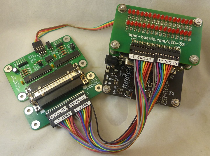
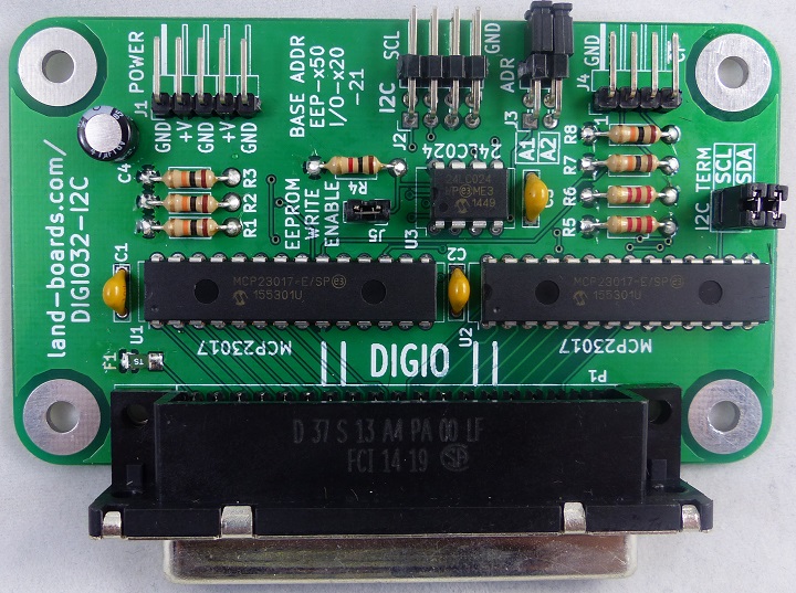
- DIGIO32-I2C - 32-bits of Digital I/O for testing some cards
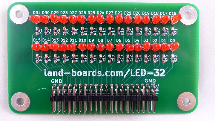
- LED-32 - 32 LEDS for bounce across LEDs tests
- DB37RIBBON - DB-37 Male to right angle Ribbon cable header
- DB-37 plugs into Test Station DIGIO32-I2C
- Some UUT cards use a second DB37RIBBON card
- DB25RIBBON - DB-25 Male or Female to Ribbon cable
- Some UUT cards have DB-25 connectors
- UUT cable sets
- Connect to DB37RIBBON, DB25RIBBON, or LED-32 cards in Test Station
- PC running PuTTY
- 9600 baud
- USB-C cable
- USB connected to PC and USB-C connected to BLACK-PILL-HUB
- Powered through the USB-C connector on the STM32 Black Pill
BLACK-PILL-HUB
LED-32
DIGIO32-I2C
Personality EEPROM
- Tests cards without personality EEPROM
- Tests cards with personality EEPROM
- Personality EEPROM follows Raspberry Pi Hat EEPROM format
- Test station writes EEPROM
- Test station uses EEPROM contents (if present) to determine which test to run
Example Personality EEPROM - DIGIO-128
Reading EEPROM
Family=ODAS
Company=land-boards.com
Product=DIGIO-128
Black Pill Setup
Resources
- Plenty of resources
- EEPROM - 524288 bytes
- SRAM - 131072 bytes
Sketch uses 50316 bytes (9%) of program storage space. Maximum is 524288 bytes.
Global variables use 3828 bytes (2%) of dynamic memory, leaving 127244 bytes for local variables. Maximum is 131072 bytes.
Programming
Programming Setup
- Steps from Programming|Program STM32 Black Pill (STM32F401 / F411) with Arduino IDE (Windows OS)
- Add the URL to Additional Board Manager URLs text box:
- Go to Tools > Board > Boards Manager
- Search for STM32, select latest version and click Install.
- Download and install STM32CubeProg from ST.com: [1]
DFU Programming
- Start the STM32CubeProg
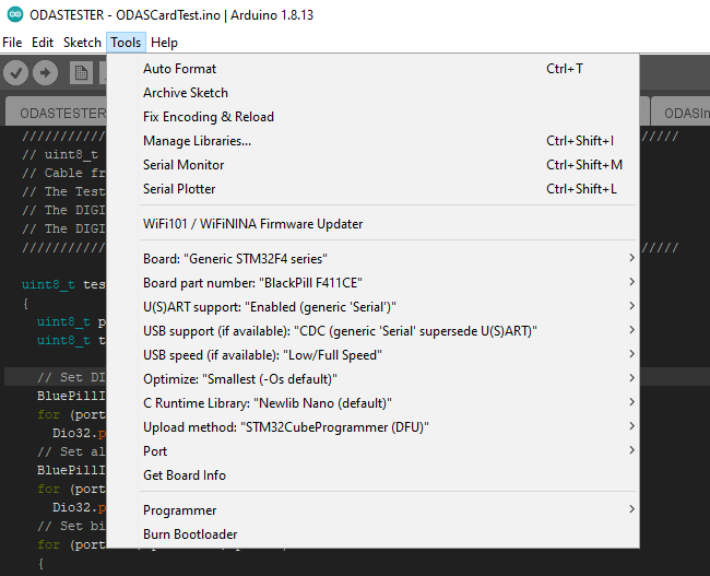
- From the Tools > Board > STM32 Board, select Generic STM32F4 series
- Select Tools > Board Part Number > BlackPill F411CE
- Under USB Support, select CDC (generic "Serial" supersede U(S)ART)
- Under Upload method, select SMT32CubeProgrammer(DFU)
- Use the onboard BOOT0 and NRST button to put the board into bootloader mode:
- press and hold the BOOT0 button
- press and release NRST (reset) button to power cycle the processor
- alternate is to press the Reset button on the BLACK-PILL-HUB card
- release BOOT0 button
- Sometimes removing the USB cable and plugging it back in while pressing BOOT0 button works better
- Upload sketch
- Displays in IDE
USB speed   : Full Speed (12MBit/s)
Manuf. ID   : STMicroelectronics
Product ID  : STM32  BOOTLOADER
SN          : 348C35983539
FW version  : 0x011a
Device ID   : 0x0431
Device name : STM32F411xC/E
Flash size  : 512 KBytes (default)
Device type : MCU
Device CPU  : Cortex-M4


Memory Programming ...
Opening and parsing file: ODASTESTER.ino.bin
  File          : ODASTESTER.ino.bin
  Size          : 49132 Bytes
  Address       : 0x08000000


Erasing memory corresponding to segment 0:
Erasing internal memory sectors [0 2]
erasing sector 0000 @: 0x08000000 done
erasing sector 0001 @: 0x08004000 done
erasing sector 0002 @: 0x08008000 done
Download in Progress:


File download complete
Time elapsed during download operation: 00:00:02.263

RUNNING Program ...
  Address:      : 0x8000000
Start operation achieved successfully
Other Programming
- ST-LINK V2
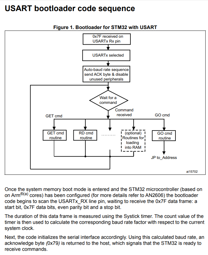
- FLASHER-STM32 - STM32 Flash loader demonstrator (UM0462)
- From AN3155
Useful Arduino Code
Here's some useful pieces of Arduino code
Wait for Host Serial to Connect
  Serial.begin(9600);
  while (!Serial);    // wait for serial port to connect. Needed for native USB
uint8_t checkI2CAddr(uint8_t addr)
Check if there is an I2C device at an address
////////////////////////////////////////////////////////////////////////////
// uint8_t checkI2CAddr(uint8_t addr) - Check that an I2C device is present
// Pass: addr - I2C address
// Returns:
//      0 : success
//      1 : data too long to fit in transmit buffer
//      2 : received NACK on transmit of address
//      3 : received NACK on transmit of data
//      4 : other error
////////////////////////////////////////////////////////////////////////////

uint8_t checkI2CAddr(uint8_t addr)
{
  Wire.beginTransmission(addr);
  return (Wire.endTransmission());
}
uint8_t checkIfMCP23017(uint8_t addr)
Check if an I2C device is an MCP23017 at an address
////////////////////////////////////////////////////////////////////////////
//  uint8_t checkIfMCP23017(uint8_t addr)
//  Check to see if the I2C part is a MCP23017
//    The GPU Pullup A register (internal register address 0x0c) is present
//    in a MCP23017 but not in a MCP23008.
//  Pass: addr - I2C address
//  Returns
//    0 : Not an MCP23017
//    1 : Likely an MCP23017
////////////////////////////////////////////////////////////////////////////

uint8_t checkIfMCP23017(uint8_t addr)
{
  // Write 0x55 to MCP23017_GPPUA (0x0c)
  Wire.beginTransmission(addr);
  Wire.write(0x0c);
  Wire.write(0x55);
  Wire.endTransmission(1);
  // Read back
  Wire.beginTransmission(addr);
  Wire.write(0x0c);
  Wire.endTransmission();
  Wire.requestFrom(addr,  1);
  if (Wire.read() == 0x55)
  {
    Serial.println(F("Detected MCP23017"));
    return 1;
  }
  else
  {
    Serial.println(F("Detected MCP23008"));
    return 0;
  }
}
Cards Supported
Goal is to have automated tests for as many cards as possible. The currently tested cars are.
- DigIO16-I2C board
- DIGIO-128 board
- OptoIn8-I2C board
- OptoOut8-I2C board
- DIGIO32-I2C board
- PROTO16-I2C board
- ODAS-PSOC5 board
- ODAS-RELAY-16 board
- DIGIO-128/64 board
- I2CIO-8 board
- I2CIO-8X board
- SWLEDX8-I2C board
- OPTOFAST-2/OptoSmall Non-Inverting board
- OPTOFAST-2/OptoSmall Inverting board
- I2C-RPT board
- I2C-RPT-08 board
- OptoFastBi board
Menu Options
Select the board type
1 - DIGIO16-I2C board
2 - DIGIO-128 board
3 - OptoIn8-I2C board
4 - OptoOut8-I2C board
5 - DIGIO32-I2C board
6 - PROTO16-I2C board
7 - ODAS-PSOC5 board
8 - ODAS-RELAY16 board
A - DIGIO-128/64 board
9 - TBD board
X - Boards without EEPROMs
Select board > X
Select the board type
1 - I2CIO8 board
2 - I2CIO8X board
3 - SWLEDX8-I2C board
4 - OPTOFast/Small Non-Inverting board
5 - OPTOFast/Small Inverting board
6 - I2C-RPT-01 board
7 - I2C-RPT-08 board
8 - OptoFastBi board
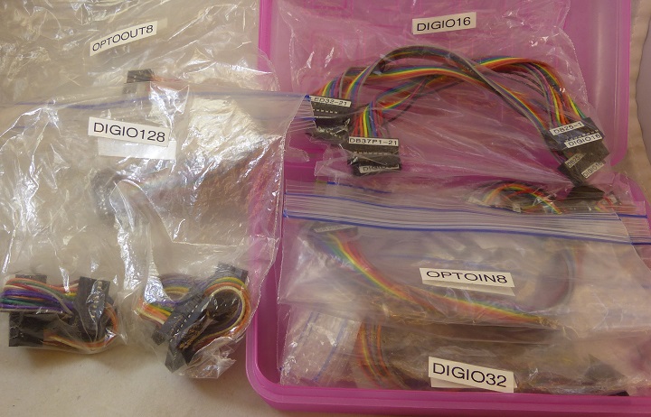
Cable Sets
- Particular cable sets for cards
- Bounce LED and Loopback to Test Station Cables
Software
- ODAS Test Software Github Repo
- Bounce LEDs and loop test to DIGIO32-I2C
