Difference between revisions of "Open Data Acquisition System"
Blwikiadmin (talk | contribs) |
Blwikiadmin (talk | contribs) |
||
| (75 intermediate revisions by 2 users not shown) | |||
| Line 1: | Line 1: | ||
| − | = | + | <video type="youtube">-W31AJnIPHI</video> |
| − | The Open Data Acquisition System consists of a Data Acquisition Processor (DAP) and | + | [[file:DIGIO32-I2C_P1994_720px.jpg]] |
| + | |||
| + | == Features == | ||
| + | |||
| + | * This document is the ODAS (Open Data Acquisition System) card design specification | ||
| + | * ODAS features a powerful combination of Open Hardware and Open Software | ||
| + | ** ODAS form factor is an open form factor which provides an inexpensive and small card size (approx 4" square) | ||
| + | * Standalone use or control low level hardware interfaces from a Host Computer | ||
| + | * Mix and match card types | ||
| + | |||
| + | === ODAS System Block Diagram === | ||
| + | |||
| + | The Open Data Acquisition System consists of a Data Acquisition Processor (DAP) and I/O cards. | ||
The block diagram is: | The block diagram is: | ||
| Line 7: | Line 19: | ||
[[File:ODAS Block Diagram.png]] | [[File:ODAS Block Diagram.png]] | ||
| − | == | + | === Maximum Configuration === |
| − | + | * MCP23017 (16 port I/O expander) uses (1) I2C address in range 0x20-0x27 | |
| + | * I2C supports up to 8 MCP23017 I2C addresses typically | ||
| + | * Up to 64 cards can be supported with a single [I2C-RPT-08|8 port I2C repeater]] | ||
| + | ** Ex: If a [[DIGIO-128]] card is used with an [[I2C-RPT-08|8 port I2C repeater]], this provides 1024 digital I/O pins | ||
| + | * Up to 8 of [[I2C-RPT-08|8 port I2C repeaters]] can be used | ||
| + | ** (64) [[DIGIO-128]] cards would result in 8,192 bits of digital I/O | ||
| + | ** Each [[I2C-RPT-08|8 port I2C repeater]] has a base address of 0x70-0x77 | ||
| − | + | == Open Hardware == | |
* Support for standard microprocessors such as Arduino, Raspberry Pi, BeagleBone Black | * Support for standard microprocessors such as Arduino, Raspberry Pi, BeagleBone Black | ||
| + | ** [[PiPicoMite02|Raspberry Pi Pico CPU]] | ||
| + | ** [[BLACK-PILL-HUB|STMF4XX "Black Pill" CPU"]] | ||
| + | ** [[BLUE-PILL-HUB|STM32F103 "Blue Pill" CPU]] | ||
| + | ** [[UNO-DB25|Arduino UNO CPU]] | ||
** ATMEGA32U4 [http://arduino.cc/en/Main/arduinoBoardLeonardo Arduino Leonardo] compatible Processor | ** ATMEGA32U4 [http://arduino.cc/en/Main/arduinoBoardLeonardo Arduino Leonardo] compatible Processor | ||
| + | ** [[ODAS-PSOC5|PSOC5 CPU]] | ||
* Industry-Standard USB Host Interface | * Industry-Standard USB Host Interface | ||
* Industry-Standard I2C Bus Interface to cards | * Industry-Standard I2C Bus Interface to cards | ||
| − | |||
| − | |||
| − | |||
| − | === | + | === Mechanicals === |
| + | |||
| + | <video type="youtube">yfm2ZRHHBAg</video> | ||
| + | |||
| + | * Standardized form factor and mechanicals | ||
| + | * Two basic form factors | ||
| + | ** 95x95mm | ||
| + | ** 49x49mm | ||
| + | * Adapter to allow both form factors to be used | ||
| + | ** Solid mounting holea | ||
| + | ** 95x95mm has (4) 6-32 holes | ||
| + | ** 49x49mm has (4) 4-40 holes | ||
| + | |||
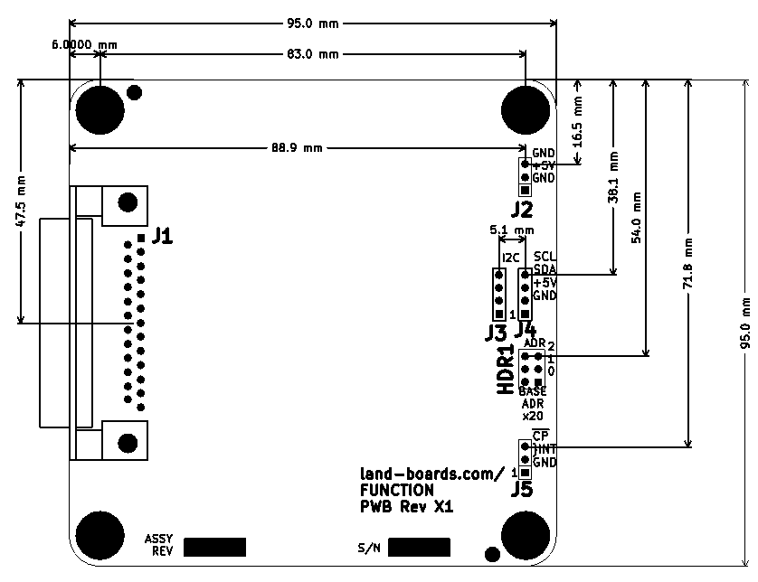
| + | ==== 95x95mm Form Factor ==== | ||
| + | |||
| + | * 6-32 screw holes in each corner | ||
| + | |||
| + | [[file:ODAS_95mm_Mechs.PNG]] | ||
| + | |||
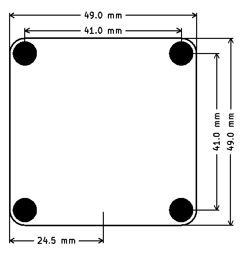
| + | ==== 49x49mm Form Factor ==== | ||
| + | |||
| + | * 4-40 screw holes in each corner | ||
| − | + | [[file:ODAS_49mm_Mechs.PNG]] | |
| − | |||
| − | |||
| − | |||
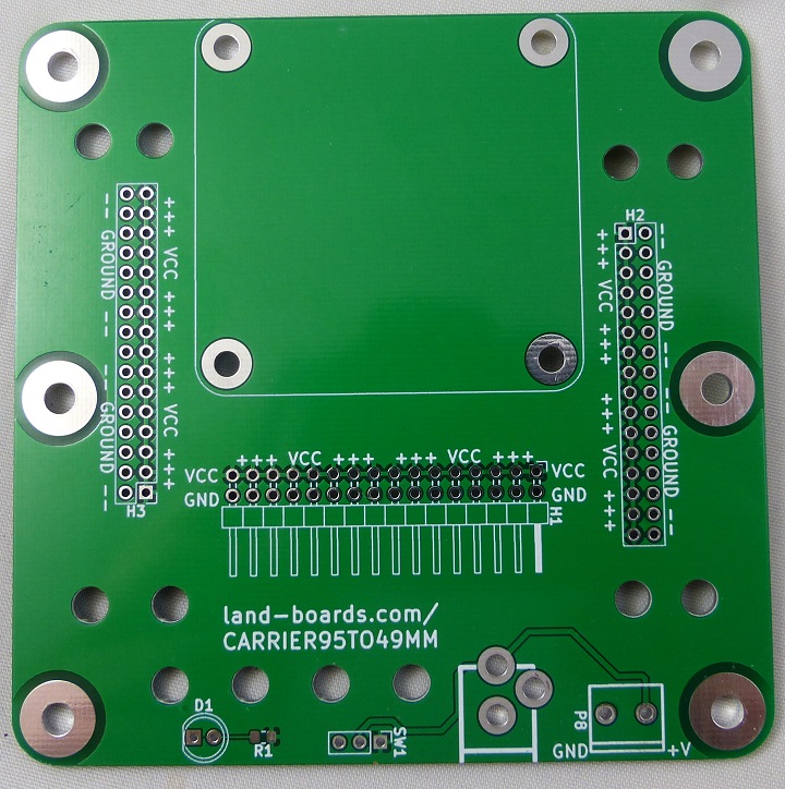
| − | == | + | ==== Mixed 95x95mm and 49x49mm cards ==== |
| − | [ | + | * [[CARRIER95TO49MM|95mm to 49mm Adapter card]] |
| − | + | [[file:P1748-CROPPED-720PX.jpg]] | |
| − | + | == Open Software == | |
| − | = | + | * USB Interface runs industry standard Firmata |
| + | * Processor card runs Arduino Leonardo compatible software | ||
| + | * Arduino "[http://playground.arduino.cc/Main/WireLibraryDetailedReference Wire]" Standard I2C bit driver | ||
| + | * Community supported [http://land-boards.com/blwiki/index.php?title=ODAS_Python_Driver Python], C++, Ruby, LabView, VxWorks drivers | ||
| − | + | === Drivers === | |
| − | |||
| − | |||
| − | |||
| − | |||
| − | |||
| − | |||
| − | |||
| − | |||
| − | |||
| − | |||
| − | |||
| − | |||
| − | |||
| − | |||
| − | |||
| − | |||
| − | === | + | ==== Arduino ==== |
| − | + | * [https://github.com/adafruit/Adafruit-MCP23008-library Adafruit MCP23008 driver] | |
| − | + | * [https://github.com/adafruit/Adafruit-MCP23017-Arduino-Library Adafruit MCP23017 driver] | |
| − | |||
| − | |||
| − | |||
| − | |||
| − | |||
| − | |||
| − | |||
| − | |||
| − | |||
| − | |||
| − | |||
| − | |||
| − | |||
| − | |||
| − | == | + | ===== Host Software - Firmata ===== |
| − | + | [https://github.com/firmata Firmata] is a [https://github.com/firmata/protocol generic protocol] for communicating with microcontrollers from software on a host computer. It is intended to work with any host computer software package. Right now there is a matching object in a number of languages. It is easy to add objects for other software to use this protocol. Basically, this firmware establishes a protocol for talking to the Arduino from the host software. The aim is to allow people to completely control the Arduino from software on the host computer. | |
| − | + | Firmata has an [http://www.firmata.org/wiki/Main_Page#Firmata_Test_Program attractive Test Program User Interface] which could be easily extended | |
| − | |||
| − | + | [[File:Firmata_test_screenshot.png]] | |
| − | + | ==== Raspberry Pi ==== | |
| − | |||
| − | |||
| − | ==== lsmod dump with DIGIO-128 card attached ==== | + | * [http://www.raspberrypi-spy.co.uk/2014/11/enabling-the-i2c-interface-on-the-raspberry-pi/ Enabling The I2C Interface On The Raspberry Pi] |
| + | * [https://learn.adafruit.com/mcp230xx-gpio-expander-on-the-raspberry-pi/using-the-library MCP230xx GPIO Expander on the Raspberry Pi] | ||
| + | * [https://github.com/adafruit/Adafruit-Raspberry-Pi-Python-Code Adafruit library code for Raspberry Pi] | ||
| + | |||
| + | ===== lsmod dump with DIGIO-128 card attached ===== | ||
<pre> | <pre> | ||
| Line 106: | Line 118: | ||
</pre> | </pre> | ||
| − | ==== Raspberry Pi Performance with DIGIO-128 card attached ==== | + | ===== Raspberry Pi Performance with DIGIO-128 card attached ===== |
| + | |||
* sudo python Adafruit_MCP230xx.py | * sudo python Adafruit_MCP230xx.py | ||
* Clock runs at 100 KHz | * Clock runs at 100 KHz | ||
| − | [File:RPi-I2C-DIGIO-128-clk-data.png]] | + | [[File:RPi-I2C-DIGIO-128-clk-data.png]] |
* Overall timing - 1 cycle | * Overall timing - 1 cycle | ||
| − | [File:RPi-I2C-DIGIO-128-overall-read-1cycle.png]] | + | [[File:RPi-I2C-DIGIO-128-overall-read-1cycle.png]] |
* Overall timing - 2 cycle (Read-modify-write) | * Overall timing - 2 cycle (Read-modify-write) | ||
| − | [File:RPi-I2C-DIGIO-128-overall-rmw-2cycles.png | + | [[File:RPi-I2C-DIGIO-128-overall-rmw-2cycles.png]] |
| + | |||
| + | ==== ESP32 MicroPython Drivers ==== | ||
| + | |||
| + | * [https://github.com/land-boards/lb-Python-Code/tree/master/MicroPython/ESP32/libraries MicroPython Drivers and Libraries for ODAS cards] | ||
| + | |||
| + | ==== PyBoard MicroPython Drivers ==== | ||
| + | |||
| + | * [https://github.com/land-boards/lb-Python-Code/tree/master/MicroPython/PyBoard%20Clone MicroPython Drivers and Libraries for ODAS cards] | ||
| + | |||
| + | ==== Raspberry Pi Pico ==== | ||
| − | + | * [https://github.com/land-boards/RasPiPico/tree/main/PicoMite_MMBASIC/PicoMite_VGA/Land%20Boards%20BASIC%20Programs/lbcards MMBasic example code] | |
| − | + | === Personality EEPROM === | |
| − | == | + | * Useful when there are a lot of I2C cards in a system |
| + | ** Useful in card test | ||
| + | ** Configure the card once, autodetect later | ||
| + | * EEPROM I2C base address = 0x50 | ||
| + | ** I2C address offset (0x50-0x57) set by jumpers for MCP23008/MCP23017 I2C port expanders | ||
| + | * [https://www.mouser.com/ProductDetail/579-24LC024-P 24LC024 EEPROM] | ||
| + | ** 256x8 | ||
| + | ** 2.5-5.5 V | ||
| + | ** Maximum Clock Frequency: 400 kHz | ||
| + | ** Supply Current - Max: 3 mA | ||
| + | * Based on [https://github.com/raspberrypi/hats/blob/master/eeprom-format.md Raspberry Pi Hat Spec] | ||
| + | <pre> | ||
| + | struct eep_vals | ||
| + | { | ||
| + | char signature[4]; // 0-3 - "ODAS" in ASCII | ||
| + | byte fmt_version; // 4 - EEPROM data format version (0x00 reserved, 0x01 = first version) | ||
| + | byte rsvd; // 5 - set to 0 | ||
| + | short numatoms; // 6-7 - set to 2 | ||
| + | long eeplen; // 8-11 - set to 96 dec | ||
| + | byte uuid[16]; // 12-27 - "0000000000000000" in ASCII | ||
| + | short pid; // 28-29 - See PID table | ||
| + | byte vslen; // 30 - set to 32 dec | ||
| + | byte pslen; // 31 - set to 32 dec | ||
| + | byte vstr[32]; // 32-63 - Vendor Null terminated String | ||
| + | byte pstr[32]; // 64-95 - Product Null terminated String | ||
| + | }; | ||
| + | </pre> | ||
| − | * | + | * Addresses 96-255 are user programable |
| + | * Addresses 0-95 can be changed by user (if desired) | ||
| − | == | + | ==== Product ID Table ==== |
| − | == | + | <pre> |
| + | Signature=ODAS | ||
| + | Vendor=land.boards.com | ||
| + | </pre> | ||
| + | <pre> | ||
| + | ProductID (in dec) Product (string) | ||
| + | 1 DigIO16-I2C | ||
| + | 2 DIGIO-128 | ||
| + | 3 DIGIO-128/64 | ||
| + | 4 OptoIn8-I2C | ||
| + | 5 OptoOut8-I2C | ||
| + | 6 DIGIO32-I2C | ||
| + | 7 PROTO16-I2C | ||
| + | 8 ODAS-PSOC5 | ||
| + | 9 ODAS-RELAY16 | ||
| + | 127 NEW CARD | ||
| + | </pre> | ||
| − | + | == Cards == | |
| − | * | + | * Various cards |
| − | * | + | ** Processor cards |
| − | * | + | ** Digital I/O cards |
| − | * | + | ** Optoisolator cards |
| − | + | ** FPGA cards | |
| − | |||
| − | * | ||
| − | * | ||
| − | |||
| − | * | ||
| − | * | ||
| − | * | ||
| − | |||
=== ODAS Processor Cards === | === ODAS Processor Cards === | ||
| Line 158: | Line 216: | ||
* UNO-DB25 - Arduino Uno with a DB-25 connector | * UNO-DB25 - Arduino Uno with a DB-25 connector | ||
* DAS-32U4 - Data Acquisition System Processor DAS-32U4 | * DAS-32U4 - Data Acquisition System Processor DAS-32U4 | ||
| + | |||
| + | === ODAS Digital I/O Cards === | ||
| + | |||
| + | <video type="youtube">ATtKuo6iPzM</video> | ||
| + | |||
| + | {| class="wikitable" | ||
| + | ! Card | ||
| + | ! Function | ||
| + | ! Interface type | ||
| + | |- | ||
| + | | [[CARRIER95TO49MM]] | ||
| + | | Adapt ODAS 49mm to 95mm cards | ||
| + | | N/A | ||
| + | |- | ||
| + | | [[DCE]] | ||
| + | | RS-232/TTL Converter | ||
| + | | TTL | ||
| + | |- | ||
| + | | [[DTE]] | ||
| + | | RS-232/TTL Converter | ||
| + | | TTL | ||
| + | |- | ||
| + | | [[DIGIO-128]] | ||
| + | | 128-bit Digital I/O Card | ||
| + | | I2C | ||
| + | |- | ||
| + | | [[DIGIO32-I2C]] | ||
| + | | 32-bit Digital I/O Card | ||
| + | | I2C | ||
| + | |- | ||
| + | | [[DigIO16-I2C]] | ||
| + | | 16-bit Digital I/O Card | ||
| + | | I2C | ||
| + | |- | ||
| + | | [[Front Panel For 8 Bit Computers]] | ||
| + | | Front Panel for 8-bit Microprocessors with I2C interfaces (SMT) | ||
| + | | I2C | ||
| + | |- | ||
| + | | [[Front Panel for 8 Bit Computers V2]] | ||
| + | | Front Panel for 8-bit Microprocessors with I2C interfaces (Thru-hole) | ||
| + | | I2C | ||
| + | |- | ||
| + | | [[I2CIO16-DB25]] | ||
| + | | 16-bit I2C I/O based on the MCP23017 | ||
| + | | I2C | ||
| + | |- | ||
| + | | [[I2CIO-8X]] | ||
| + | | 8-bit I2C I/O based on the MCP23008 | ||
| + | | I2C | ||
| + | |- | ||
| + | | [[I2CIO-8]] | ||
| + | | 8-bit I2C I/O based on the MCP23008 | ||
| + | | I2C | ||
| + | |- | ||
| + | | [[I2C-TEMP]] | ||
| + | | I2C Temperature Sensor | ||
| + | | I2C | ||
| + | |- | ||
| + | | [[I2C-RPT]] | ||
| + | | 4-Channel I2C Multiplexer/Repeater | ||
| + | | I2C | ||
| + | |- | ||
| + | | [[I2C-RPT-08]] | ||
| + | | 8-channel I2C Multiplexer/Repeater | ||
| + | | I2C | ||
| + | |- | ||
| + | | [[ODAS-PSOC5]] | ||
| + | | Programmable System On a Chip | ||
| + | | I2C, SPI, TTL | ||
| + | |- | ||
| + | | [[ODAS-RELAY-16]] | ||
| + | | 16 Channel Relay Card | ||
| + | | I2C | ||
| + | |- | ||
| + | | [[PROTO16-I2C]] | ||
| + | | 16-bit I/O with prototyping area | ||
| + | | I2C | ||
| + | |- | ||
| + | | [[PS2X49]] | ||
| + | | PS/2 keyboard/mouse interface | ||
| + | | TTL | ||
| + | |- | ||
| + | | [[SWLEDX8]] | ||
| + | | 8 Switches and 8 LEDs | ||
| + | | I2C | ||
| + | |- | ||
| + | | [[SWLEDX8-I2C]] | ||
| + | | 16 bit I2C connection to SWLEDX8 card | ||
| + | | I2C | ||
| + | |- | ||
| + | | [[TinyPS2]] | ||
| + | | PS/2 keyboard or mouse to TTL Level Serial converter | ||
| + | | TTL | ||
| + | |- | ||
| + | | [[VGAX49]] | ||
| + | | VGA Digital Connection (2:2:2 or 5:6:5) | ||
| + | | TTL/Analog | ||
| + | |- | ||
| + | | [[SD_CARD_X49]] | ||
| + | | SD Card Adapter | ||
| + | | TTL | ||
| + | |- | ||
| + | |} | ||
| + | |||
| + | === ODAS FPGA Cards === | ||
| + | |||
| + | * [[RETRO-EP4CE15]] - QMTECH Cyclone IV or V FPGA cards | ||
| + | * [[RETRO-EP4]] - Waveshare EP4CE6 FPGA card | ||
| + | * [[EP2C5-DB]] - Cyclone II FPGA card | ||
| + | |||
| + | ==== ODAS Opto-Isolated Cards ==== | ||
| + | |||
| + | [[file:OptoIn8-I2C-X3-CCA-5456-720px.jpg]] | ||
| + | |||
| + | Optically Isolated cards are necessary to connect together different electrical system without concerns for ground loops, voltage dropes or electrical noise. ODAS offers two optically isolated cards; one for input and one for output. | ||
| + | |||
| + | * [[OptoIn8-I2C]] - 8-Channel Optically Isolated Input Card | ||
| + | * [[OptoOut8-I2C]] - 8-Channel Optically Isolated Output Card | ||
== ODAS Card Test Station == | == ODAS Card Test Station == | ||
| − | * ODAS Test Station | + | * [[Arduino Based_Test Station|ODAS Test Station]] |
* ODAS Tester - Test Software in GitHub repository | * ODAS Tester - Test Software in GitHub repository | ||
* Arduino Nano | * Arduino Nano | ||
Latest revision as of 10:34, 2 June 2022
Contents
Features
- This document is the ODAS (Open Data Acquisition System) card design specification
- ODAS features a powerful combination of Open Hardware and Open Software
- ODAS form factor is an open form factor which provides an inexpensive and small card size (approx 4" square)
- Standalone use or control low level hardware interfaces from a Host Computer
- Mix and match card types
ODAS System Block Diagram
The Open Data Acquisition System consists of a Data Acquisition Processor (DAP) and I/O cards.
The block diagram is:
Maximum Configuration
- MCP23017 (16 port I/O expander) uses (1) I2C address in range 0x20-0x27
- I2C supports up to 8 MCP23017 I2C addresses typically
- Up to 64 cards can be supported with a single [I2C-RPT-08|8 port I2C repeater]]
- Ex: If a DIGIO-128 card is used with an 8 port I2C repeater, this provides 1024 digital I/O pins
- Up to 8 of 8 port I2C repeaters can be used
- (64) DIGIO-128 cards would result in 8,192 bits of digital I/O
- Each 8 port I2C repeater has a base address of 0x70-0x77
Open Hardware
- Support for standard microprocessors such as Arduino, Raspberry Pi, BeagleBone Black
- Raspberry Pi Pico CPU
- STMF4XX "Black Pill" CPU"
- STM32F103 "Blue Pill" CPU
- Arduino UNO CPU
- ATMEGA32U4 Arduino Leonardo compatible Processor
- PSOC5 CPU
- Industry-Standard USB Host Interface
- Industry-Standard I2C Bus Interface to cards
Mechanicals
- Standardized form factor and mechanicals
- Two basic form factors
- 95x95mm
- 49x49mm
- Adapter to allow both form factors to be used
- Solid mounting holea
- 95x95mm has (4) 6-32 holes
- 49x49mm has (4) 4-40 holes
95x95mm Form Factor
- 6-32 screw holes in each corner
49x49mm Form Factor
- 4-40 screw holes in each corner
Mixed 95x95mm and 49x49mm cards
Open Software
- USB Interface runs industry standard Firmata
- Processor card runs Arduino Leonardo compatible software
- Arduino "Wire" Standard I2C bit driver
- Community supported Python, C++, Ruby, LabView, VxWorks drivers
Drivers
Arduino
Host Software - Firmata
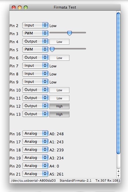
Firmata is a generic protocol for communicating with microcontrollers from software on a host computer. It is intended to work with any host computer software package. Right now there is a matching object in a number of languages. It is easy to add objects for other software to use this protocol. Basically, this firmware establishes a protocol for talking to the Arduino from the host software. The aim is to allow people to completely control the Arduino from software on the host computer.
Firmata has an attractive Test Program User Interface which could be easily extended
Raspberry Pi
- Enabling The I2C Interface On The Raspberry Pi
- MCP230xx GPIO Expander on the Raspberry Pi
- Adafruit library code for Raspberry Pi
lsmod dump with DIGIO-128 card attached
pi@raspi3 ~ $ lsmod | grep i2c_
i2c_dev                 5557  0
i2c_bcm2708             3997  0
pi@raspi3 ~ $ sudo i2cdetect -y 1
     0  1  2  3  4  5  6  7  8  9  a  b  c  d  e  f
00:          -- -- -- -- -- -- -- -- -- -- -- -- --
10: -- -- -- -- -- -- -- -- -- -- -- -- -- -- -- --
20: 20 21 22 23 24 25 26 27 -- -- -- -- -- -- -- --
30: -- -- -- -- -- -- -- -- -- -- -- -- -- -- -- --
40: -- -- -- -- -- -- -- -- -- -- -- -- -- -- -- --
50: 50 -- -- -- -- -- -- -- -- -- -- -- -- -- -- --
60: -- -- -- -- -- -- -- -- -- -- -- -- -- -- -- --
70: -- -- -- -- -- -- -- --
Raspberry Pi Performance with DIGIO-128 card attached
- sudo python Adafruit_MCP230xx.py
- Clock runs at 100 KHz
- Overall timing - 1 cycle
- Overall timing - 2 cycle (Read-modify-write)
ESP32 MicroPython Drivers
PyBoard MicroPython Drivers
Raspberry Pi Pico
Personality EEPROM
- Useful when there are a lot of I2C cards in a system
- Useful in card test
- Configure the card once, autodetect later
- EEPROM I2C base address = 0x50
- I2C address offset (0x50-0x57) set by jumpers for MCP23008/MCP23017 I2C port expanders
- 24LC024 EEPROM
- 256x8
- 2.5-5.5 V
- Maximum Clock Frequency: 400 kHz
- Supply Current - Max: 3 mA
- Based on Raspberry Pi Hat Spec
struct eep_vals
{
  char signature[4]; // 0-3 - "ODAS" in ASCII
  byte fmt_version;  // 4 - EEPROM data format version (0x00 reserved, 0x01 = first version)
  byte rsvd;         // 5 - set to 0
  short numatoms;    // 6-7 - set to 2
  long eeplen;       // 8-11 - set to 96 dec
  byte uuid[16];     // 12-27 - "0000000000000000" in ASCII
  short pid;         // 28-29 - See PID table
  byte vslen;        // 30 - set to 32 dec
  byte pslen;        // 31 - set to 32 dec
  byte vstr[32];     // 32-63 - Vendor Null terminated String
  byte pstr[32];     // 64-95 - Product Null terminated String
};
- Addresses 96-255 are user programable
- Addresses 0-95 can be changed by user (if desired)
Product ID Table
Signature=ODAS
Vendor=land.boards.com
ProductID (in dec)	Product (string)
1			DigIO16-I2C
2			DIGIO-128
3       		DIGIO-128/64
4			OptoIn8-I2C
5			OptoOut8-I2C
6			DIGIO32-I2C
7			PROTO16-I2C
8			ODAS-PSOC5
9			ODAS-RELAY16
127     		NEW CARD
Cards
- Various cards
- Processor cards
- Digital I/O cards
- Optoisolator cards
- FPGA cards
ODAS Processor Cards
No Data Acquistion System is complete without a Processor Card.
- BLUE-PILL-HUB - STM32 "Blue-Pill Board" based system processor
- ODAS-PSOC5 - Cypress Semiconductor Programmable System on a Chip
- NANO-BKOUT - Arduino NANO GVS Breakout card
- GVSDuino - Arduino UNO compatible GVS Processor card
- UNO-DB25 - Arduino Uno with a DB-25 connector
- DAS-32U4 - Data Acquisition System Processor DAS-32U4
ODAS Digital I/O Cards
| Card | Function | Interface type |
|---|---|---|
| CARRIER95TO49MM | Adapt ODAS 49mm to 95mm cards | N/A |
| DCE | RS-232/TTL Converter | TTL |
| DTE | RS-232/TTL Converter | TTL |
| DIGIO-128 | 128-bit Digital I/O Card | I2C |
| DIGIO32-I2C | 32-bit Digital I/O Card | I2C |
| DigIO16-I2C | 16-bit Digital I/O Card | I2C |
| Front Panel For 8 Bit Computers | Front Panel for 8-bit Microprocessors with I2C interfaces (SMT) | I2C |
| Front Panel for 8 Bit Computers V2 | Front Panel for 8-bit Microprocessors with I2C interfaces (Thru-hole) | I2C |
| I2CIO16-DB25 | 16-bit I2C I/O based on the MCP23017 | I2C |
| I2CIO-8X | 8-bit I2C I/O based on the MCP23008 | I2C |
| I2CIO-8 | 8-bit I2C I/O based on the MCP23008 | I2C |
| I2C-TEMP | I2C Temperature Sensor | I2C |
| I2C-RPT | 4-Channel I2C Multiplexer/Repeater | I2C |
| I2C-RPT-08 | 8-channel I2C Multiplexer/Repeater | I2C |
| ODAS-PSOC5 | Programmable System On a Chip | I2C, SPI, TTL |
| ODAS-RELAY-16 | 16 Channel Relay Card | I2C |
| PROTO16-I2C | 16-bit I/O with prototyping area | I2C |
| PS2X49 | PS/2 keyboard/mouse interface | TTL |
| SWLEDX8 | 8 Switches and 8 LEDs | I2C |
| SWLEDX8-I2C | 16 bit I2C connection to SWLEDX8 card | I2C |
| TinyPS2 | PS/2 keyboard or mouse to TTL Level Serial converter | TTL |
| VGAX49 | VGA Digital Connection (2:2:2 or 5:6:5) | TTL/Analog |
| SD_CARD_X49 | SD Card Adapter | TTL |
ODAS FPGA Cards
- RETRO-EP4CE15 - QMTECH Cyclone IV or V FPGA cards
- RETRO-EP4 - Waveshare EP4CE6 FPGA card
- EP2C5-DB - Cyclone II FPGA card
ODAS Opto-Isolated Cards
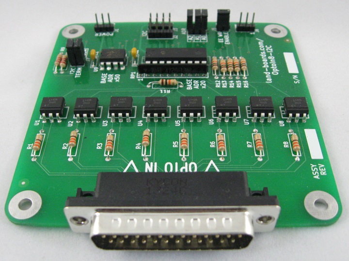
Optically Isolated cards are necessary to connect together different electrical system without concerns for ground loops, voltage dropes or electrical noise. ODAS offers two optically isolated cards; one for input and one for output.
- OptoIn8-I2C - 8-Channel Optically Isolated Input Card
- OptoOut8-I2C - 8-Channel Optically Isolated Output Card
ODAS Card Test Station
- ODAS Test Station
- ODAS Tester - Test Software in GitHub repository
- Arduino Nano
- Cables or loopback connector
- Auto-detect card if test has been run before
- Presents card type list for un-programmed EEPROMs
Checking EEPROM for board type...Detected DIGIO-128 board
R=Read EEPROM, W=Write EEPROM, T=Test DIGIOs, L=Loop Test, B=Bounce LEDs
