Difference between revisions of "RETRO-EP4"
Jump to navigation
Jump to search
Blwikiadmin (talk | contribs) |
Blwikiadmin (talk | contribs) |
||
| (29 intermediate revisions by the same user not shown) | |||
| Line 13: | Line 13: | ||
== Features == | == Features == | ||
| − | + | * [https://github.com/douggilliland/MultiComp/wiki Full MultiComp Support] of classic 8-bit Retrocomputers | |
| − | + | ** [https://github.com/douggilliland/MultiComp/wiki/Land-Boards-MultiComp-Builds#Z80 Z80] | |
| + | ** [https://github.com/douggilliland/MultiComp/wiki/Land-Boards-MultiComp-Builds#6502 6502] | ||
| + | ** [https://github.com/douggilliland/MultiComp/wiki/Land-Boards-MultiComp-Builds#6809 6809] | ||
| + | ** [https://github.com/douggilliland/MultiComp/wiki/Land-Boards-MultiComp-Builds#6800 6800] | ||
| + | * Mounts [https://www.waveshare.com/wiki/CoreEP4CE6 Waveshare CoreEP4CE6 - EP4CE6E22C8N FPGA Card] - Wiki page | ||
| + | ** [https://www.aliexpress.com/item/830309351.html?spm=a2g0o.productlist.0.0.1648250fqwQfoX AliExpress listing] - $27 | ||
| + | ** [https://www.amazon.com/CoreEP4CE6-Development-EP4CE6E22C8N-Interface-Programming/dp/B08BLFK7C2/ref=sr_1_14?dchild=1&keywords=WaveShare+CoreEP4CE6&qid=1598101893&sr=8-14 Amazon listing] - $33 (faster) | ||
* 6 bit video on VGA | * 6 bit video on VGA | ||
| − | * PS/2 connector | + | ** 2:2:2 (R:G:B) |
| − | * 512KB of SRAM for banked use in CP/M | + | * PS/2 connector for keyboard |
| + | * 512KB of 8-bit SRAM for banked use in CP/M | ||
* Mount for inexpensive FTDI USB to serial converter | * Mount for inexpensive FTDI USB to serial converter | ||
| + | ** Hardware handshake for high speed serial | ||
* SD Card | * SD Card | ||
| − | * DC power jack | + | * Headers for extra I/O |
| + | * 5V DC power jack | ||
| + | |||
| + | === FPGA Resources === | ||
| + | |||
| + | [[File:EP4CExx_Resources.PNG]] | ||
| + | |||
== VGA - Ideal Drive 2:2:2 Case == | == VGA - Ideal Drive 2:2:2 Case == | ||
| − | * | + | * FPGA has a 3.3V driver which can drive 8 mA |
* Ideal case drive current | * Ideal case drive current | ||
** 0.7V into 75 Ohms = 9.33 mA | ** 0.7V into 75 Ohms = 9.33 mA | ||
| Line 44: | Line 58: | ||
* [http://land-boards.com/RETRO-EP4/RETRO-EP4_Schematic_Rev_X1.pdf Rev X1 schematic] | * [http://land-boards.com/RETRO-EP4/RETRO-EP4_Schematic_Rev_X1.pdf Rev X1 schematic] | ||
* [http://land-boards.com/RETRO-EP4/RETRO-EP4_Schematic_Rev_X2.pdf Rev X2 schematic] | * [http://land-boards.com/RETRO-EP4/RETRO-EP4_Schematic_Rev_X2.pdf Rev X2 schematic] | ||
| + | |||
| + | == Programming the FPGA EEPROM == | ||
| + | |||
| + | * File | ||
| + | * Convert Programming File | ||
| + | * Configuration Device = EPCS16 | ||
| + | * Mode = Active Serial | ||
| + | * Programming File Type: *.jic | ||
| + | * Advanced = Check both Disables... | ||
| + | * Select Flash Loader | ||
| + | * Add Device = Cyclone IV and EP4CE15 | ||
| + | * Select SOF Data | ||
| + | * Select Add File and select the .sof file | ||
| + | * Generate | ||
| + | * In Tools, Programmer | ||
| + | * Add file and select the .jic file | ||
| + | * Select Program/Configure | ||
| + | * Takes a while to program | ||
| + | * Press button near VGA | ||
== Multicomp Builds == | == Multicomp Builds == | ||
| Line 52: | Line 85: | ||
<pre> | <pre> | ||
| + | set_global_assignment -name FAMILY "Cyclone IV E" | ||
| + | set_global_assignment -name DEVICE EP4CE6E22C8 | ||
| + | set_global_assignment -name TOP_LEVEL_ENTITY Microcomputer | ||
| + | set_global_assignment -name ORIGINAL_QUARTUS_VERSION "13.0 SP1" | ||
| + | set_global_assignment -name PROJECT_CREATION_TIME_DATE "17:55:48 OCTOBER 20, 2013" | ||
| + | set_global_assignment -name LAST_QUARTUS_VERSION "18.1.0 Lite Edition" | ||
| + | set_global_assignment -name PROJECT_OUTPUT_DIRECTORY output_files | ||
| + | set_global_assignment -name PARTITION_NETLIST_TYPE SOURCE -section_id Top | ||
| + | set_global_assignment -name PARTITION_FITTER_PRESERVATION_LEVEL PLACEMENT_AND_ROUTING -section_id Top | ||
| + | set_global_assignment -name PARTITION_COLOR 16764057 -section_id Top | ||
| + | set_global_assignment -name MIN_CORE_JUNCTION_TEMP 0 | ||
| + | set_global_assignment -name MAX_CORE_JUNCTION_TEMP 85 | ||
| + | set_global_assignment -name DEVICE_FILTER_PACKAGE TQFP | ||
| + | set_global_assignment -name DEVICE_FILTER_PIN_COUNT 144 | ||
| + | set_global_assignment -name DEVICE_FILTER_SPEED_GRADE 8 | ||
| + | # Clocks and reset | ||
set_location_assignment PIN_23 -to clk | set_location_assignment PIN_23 -to clk | ||
| − | |||
| − | |||
set_location_assignment PIN_125 -to n_reset | set_location_assignment PIN_125 -to n_reset | ||
set_instance_assignment -name WEAK_PULL_UP_RESISTOR ON -to n_reset | set_instance_assignment -name WEAK_PULL_UP_RESISTOR ON -to n_reset | ||
| + | # PS/2 Keyboard | ||
set_location_assignment PIN_127 -to ps2Clk | set_location_assignment PIN_127 -to ps2Clk | ||
set_location_assignment PIN_126 -to ps2Data | set_location_assignment PIN_126 -to ps2Data | ||
| + | set_instance_assignment -name WEAK_PULL_UP_RESISTOR ON -to ps2Data | ||
| + | set_instance_assignment -name WEAK_PULL_UP_RESISTOR ON -to ps2Clk | ||
| + | # Serial | ||
set_location_assignment PIN_132 -to rxd1 | set_location_assignment PIN_132 -to rxd1 | ||
set_instance_assignment -name WEAK_PULL_UP_RESISTOR ON -to rxd1 | set_instance_assignment -name WEAK_PULL_UP_RESISTOR ON -to rxd1 | ||
set_location_assignment PIN_128 -to txd1 | set_location_assignment PIN_128 -to txd1 | ||
set_location_assignment PIN_129 -to rts1 | set_location_assignment PIN_129 -to rts1 | ||
| + | # VGA Video | ||
set_location_assignment PIN_112 -to videoR1 | set_location_assignment PIN_112 -to videoR1 | ||
set_location_assignment PIN_113 -to videoR0 | set_location_assignment PIN_113 -to videoR0 | ||
| Line 71: | Line 123: | ||
set_location_assignment PIN_119 -to hSync | set_location_assignment PIN_119 -to hSync | ||
set_location_assignment PIN_121 -to vSync | set_location_assignment PIN_121 -to vSync | ||
| + | # SD Card | ||
set_location_assignment PIN_58 -to sdCS | set_location_assignment PIN_58 -to sdCS | ||
set_location_assignment PIN_60 -to sdSCLK | set_location_assignment PIN_60 -to sdSCLK | ||
set_location_assignment PIN_59 -to sdMISO | set_location_assignment PIN_59 -to sdMISO | ||
set_location_assignment PIN_55 -to sdMOSI | set_location_assignment PIN_55 -to sdMOSI | ||
| + | set_location_assignment PIN_85 -to driveLED | ||
| + | set_instance_assignment -name WEAK_PULL_UP_RESISTOR ON -to sdMISO | ||
| + | # SRAM | ||
set_location_assignment PIN_68 -to n_sRamCS | set_location_assignment PIN_68 -to n_sRamCS | ||
set_location_assignment PIN_50 -to n_sRamOE | set_location_assignment PIN_50 -to n_sRamOE | ||
| Line 105: | Line 161: | ||
set_location_assignment PIN_46 -to sramData[6] | set_location_assignment PIN_46 -to sramData[6] | ||
set_location_assignment PIN_49 -to sramData[7] | set_location_assignment PIN_49 -to sramData[7] | ||
| + | # LEDs | ||
set_location_assignment PIN_3 -to ledOut8[0] | set_location_assignment PIN_3 -to ledOut8[0] | ||
set_location_assignment PIN_7 -to ledOut8[1] | set_location_assignment PIN_7 -to ledOut8[1] | ||
set_location_assignment PIN_10 -to ledOut8[2] | set_location_assignment PIN_10 -to ledOut8[2] | ||
set_location_assignment PIN_11 -to ledOut8[3] | set_location_assignment PIN_11 -to ledOut8[3] | ||
| − | |||
| − | |||
| − | |||
</pre> | </pre> | ||
Latest revision as of 13:12, 22 August 2020
Contents
RETRO-EP4 FPGA Card
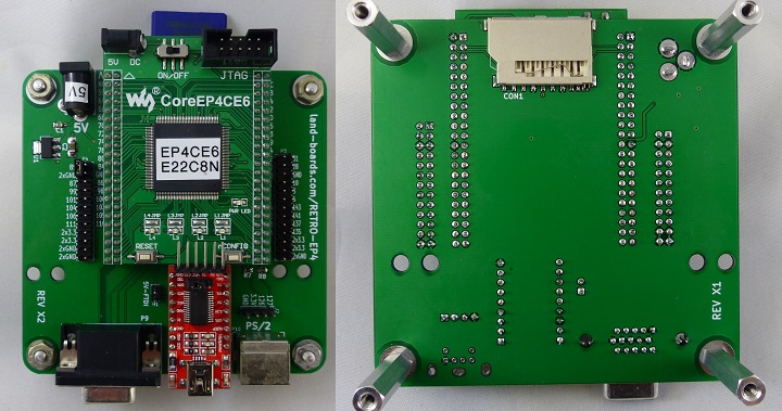
I love Grant Searle's Multicomp project. It lets you create 6502, Z80, 6809 Retrocomputers of the late 1970s era. This card provides all of the connections needed.
Grant's original design used an EP2 but that's not compatible with the latest version Altera/Intel Quartus.This upgrades to the newer EP4CE6 FPGA. We've done the work of porting the Multicomp to this card.
Features
- Full MultiComp Support of classic 8-bit Retrocomputers
- Mounts Waveshare CoreEP4CE6 - EP4CE6E22C8N FPGA Card - Wiki page
- AliExpress listing - $27
- Amazon listing - $33 (faster)
- 6 bit video on VGA
- 2:2:2 (R:G:B)
- PS/2 connector for keyboard
- 512KB of 8-bit SRAM for banked use in CP/M
- Mount for inexpensive FTDI USB to serial converter
- Hardware handshake for high speed serial
- SD Card
- Headers for extra I/O
- 5V DC power jack
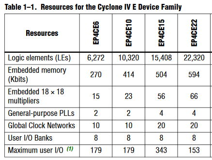
FPGA Resources
VGA - Ideal Drive 2:2:2 Case
- FPGA has a 3.3V driver which can drive 8 mA
- Ideal case drive current
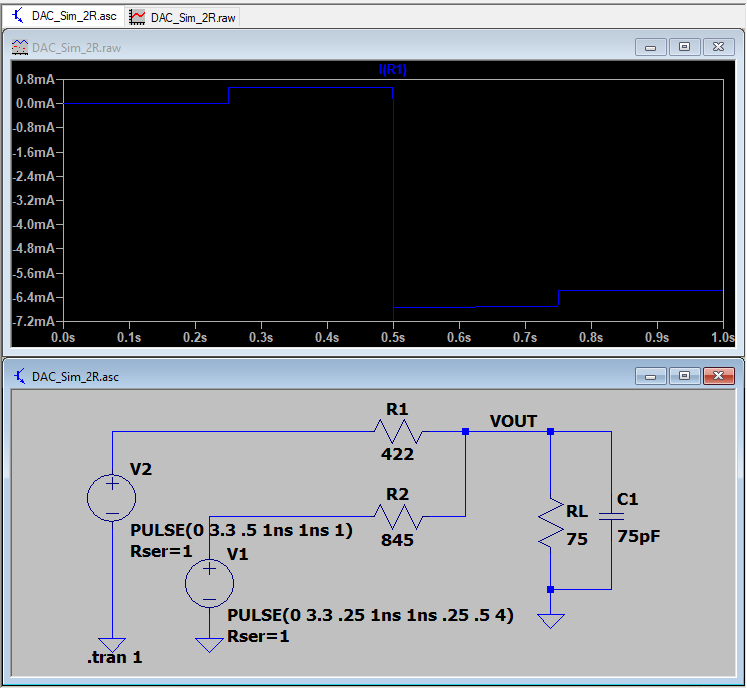
- 0.7V into 75 Ohms = 9.33 mA
- R-2R values
- Ideal resistor values are 417.9 ohms and 835.7 ohms
- Standard value 1% resistors
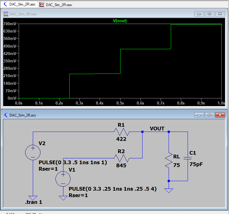
- 1% standard values are 422 (Mouser), 845 (Mouser) Ohms
- Get closest values
- 0V, 0.228V, 0.460V, 0.693V
- Voltage steps are:
- Current steps are:
Schematics
Programming the FPGA EEPROM
- File
- Convert Programming File
- Configuration Device = EPCS16
- Mode = Active Serial
- Programming File Type: *.jic
- Advanced = Check both Disables...
- Select Flash Loader
- Add Device = Cyclone IV and EP4CE15
- Select SOF Data
- Select Add File and select the .sof file
- Generate
- In Tools, Programmer
- Add file and select the .jic file
- Select Program/Configure
- Takes a while to program
- Press button near VGA
Multicomp Builds
Pin List
set_global_assignment -name FAMILY "Cyclone IV E"
set_global_assignment -name DEVICE EP4CE6E22C8
set_global_assignment -name TOP_LEVEL_ENTITY Microcomputer
set_global_assignment -name ORIGINAL_QUARTUS_VERSION "13.0 SP1"
set_global_assignment -name PROJECT_CREATION_TIME_DATE "17:55:48  OCTOBER 20, 2013"
set_global_assignment -name LAST_QUARTUS_VERSION "18.1.0 Lite Edition"
set_global_assignment -name PROJECT_OUTPUT_DIRECTORY output_files
set_global_assignment -name PARTITION_NETLIST_TYPE SOURCE -section_id Top
set_global_assignment -name PARTITION_FITTER_PRESERVATION_LEVEL PLACEMENT_AND_ROUTING -section_id Top
set_global_assignment -name PARTITION_COLOR 16764057 -section_id Top
set_global_assignment -name MIN_CORE_JUNCTION_TEMP 0
set_global_assignment -name MAX_CORE_JUNCTION_TEMP 85
set_global_assignment -name DEVICE_FILTER_PACKAGE TQFP
set_global_assignment -name DEVICE_FILTER_PIN_COUNT 144
set_global_assignment -name DEVICE_FILTER_SPEED_GRADE 8
# Clocks and reset
set_location_assignment PIN_23 -to clk
set_location_assignment PIN_125 -to n_reset
set_instance_assignment -name WEAK_PULL_UP_RESISTOR ON -to n_reset
# PS/2 Keyboard
set_location_assignment PIN_127 -to ps2Clk
set_location_assignment PIN_126 -to ps2Data
set_instance_assignment -name WEAK_PULL_UP_RESISTOR ON -to ps2Data
set_instance_assignment -name WEAK_PULL_UP_RESISTOR ON -to ps2Clk
# Serial
set_location_assignment PIN_132 -to rxd1
set_instance_assignment -name WEAK_PULL_UP_RESISTOR ON -to rxd1
set_location_assignment PIN_128 -to txd1
set_location_assignment PIN_129 -to rts1
# VGA Video
set_location_assignment PIN_112 -to videoR1
set_location_assignment PIN_113 -to videoR0
set_location_assignment PIN_114 -to videoG1
set_location_assignment PIN_115 -to videoG0
set_location_assignment PIN_124 -to videoB1
set_location_assignment PIN_120 -to videoB0
set_location_assignment PIN_119 -to hSync
set_location_assignment PIN_121 -to vSync
# SD Card
set_location_assignment PIN_58 -to sdCS
set_location_assignment PIN_60 -to sdSCLK
set_location_assignment PIN_59 -to sdMISO
set_location_assignment PIN_55 -to sdMOSI
set_location_assignment PIN_85 -to driveLED
set_instance_assignment -name WEAK_PULL_UP_RESISTOR ON -to sdMISO
# SRAM
set_location_assignment PIN_68 -to n_sRamCS
set_location_assignment PIN_50 -to n_sRamOE
set_location_assignment PIN_75 -to n_sRamWE
set_location_assignment PIN_65 -to sramAddress[0]
set_location_assignment PIN_64 -to sramAddress[1]
set_location_assignment PIN_67 -to sramAddress[2]
set_location_assignment PIN_66 -to sramAddress[3]
set_location_assignment PIN_69 -to sramAddress[4]
set_location_assignment PIN_74 -to sramAddress[5]
set_location_assignment PIN_77 -to sramAddress[6]
set_location_assignment PIN_76 -to sramAddress[7]
set_location_assignment PIN_83 -to sramAddress[8]
set_location_assignment PIN_80 -to sramAddress[9]
set_location_assignment PIN_34 -to sramAddress[10]
set_location_assignment PIN_33 -to sramAddress[11]
set_location_assignment PIN_38 -to sramAddress[12]
set_location_assignment PIN_39 -to sramAddress[13]
set_location_assignment PIN_42 -to sramAddress[14]
set_location_assignment PIN_51 -to sramAddress[15]
set_location_assignment PIN_52 -to sramAddress[16]
set_location_assignment PIN_53 -to sramAddress[17]
set_location_assignment PIN_54 -to sramAddress[18]
set_location_assignment PIN_71 -to sramData[0]
set_location_assignment PIN_70 -to sramData[1]
set_location_assignment PIN_73 -to sramData[2]
set_location_assignment PIN_72 -to sramData[3]
set_location_assignment PIN_43 -to sramData[4]
set_location_assignment PIN_44 -to sramData[5]
set_location_assignment PIN_46 -to sramData[6]
set_location_assignment PIN_49 -to sramData[7]
# LEDs
set_location_assignment PIN_3 -to ledOut8[0]
set_location_assignment PIN_7 -to ledOut8[1]
set_location_assignment PIN_10 -to ledOut8[2]
set_location_assignment PIN_11 -to ledOut8[3]


