Difference between revisions of "Z80 in 3 Chips"
Jump to navigation
Jump to search
Blwikiadmin (talk | contribs) |
Blwikiadmin (talk | contribs) |
||
| Line 62: | Line 62: | ||
=== J2, J3 - I/O Ports === | === J2, J3 - I/O Ports === | ||
| − | * J3 connects to [[JOYPAD]] | + | * J3 connects to [[JOYPAD]] on GPA connector |
[[File:Conn_J2_J3.PNG]] | [[File:Conn_J2_J3.PNG]] | ||
Revision as of 18:14, 6 September 2022
Features
- Z80
- 12.5 MHz operation
- 512KB SRAM
- PSoC5LP
- PSoC5 LP emulates standard Z80 peripheral chips
- Serial port with USB
- Memory Management Unit (MMU)
- Controls 512KB SRAM
- Loader moves EPROM code to SRAM
- Controls CPU reset
- PSoC5 LP emulates standard Z80 peripheral chips
- Optional MCP23017 16-bit port expander
- I2C Addresses 0x24
- Optional Front Panel
- I2C Addresses 0x20-0x23
- SPI interface for SDHC card
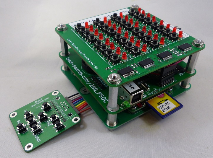
Stackup (top to bottom)
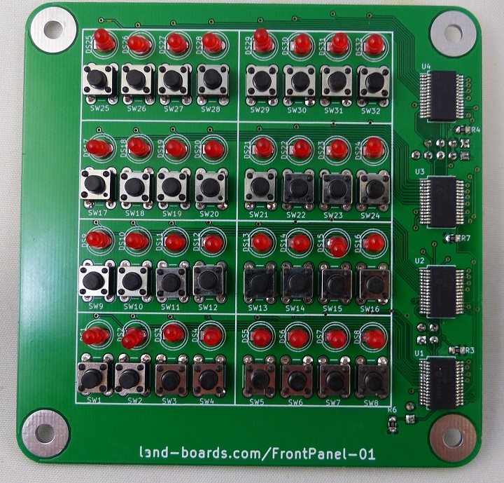
- Front Panel For 8 Bit Computers
- 32 LEDs
- 32 pushbutton switches
- I2C interface
- Z80 in 3 Chips (this card)
- SD_CARD_X49 mounted on CARRIER95TO49MM
- JOYPAD
Connectors
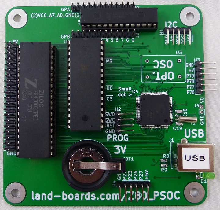
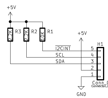
H1 - I2C Interface
- Connects to Front Panel Card via I2C
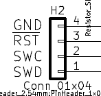
H2 - ISP Download
- Connects to PSoC programmer
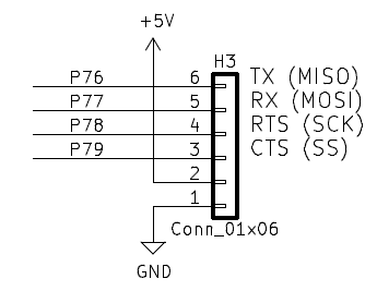
H3- Serial Port or SPI (SD Card)
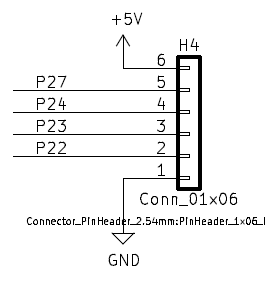
H4 - I/O
J1 - USB B
- 5V card Power
- USB to Serial comm port
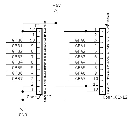
J2, J3 - I/O Ports
- J3 connects to JOYPAD on GPA connector
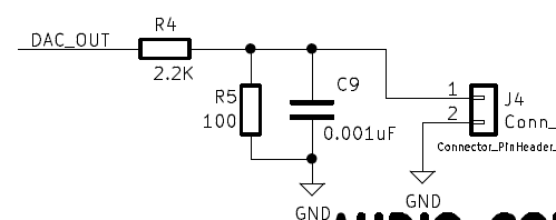
J4 - Audio Out
- DAC is the Analog function generator in the PSoC
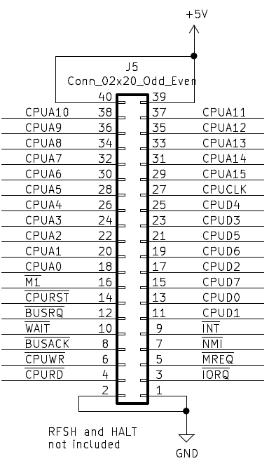
J5 - Z80 Signals
- Useful for monitoring the CPU lines
Software
- Hardware/Software options are set in the PSoC "Hardware_Config.h" file
- Comment out all but one choice
- Options
- GRANT_9_CHIP_Z80
- GRANT_7_CHIP_Z80
- GRANT_7_CHIP_Z80_STANDALONE
- GRANT_FPGA_CPM
- MULTIBOOT_CPM
Front Panel
- Card boots into Front Panel Control
- SRAM can be examined/changed in SRAM from the Front Panel
- Options to run Z80 or PSoC Monitor
- Upper right (SW32) = Increment address, read
- SW31 = Store data, increment address, read data
- SW30 = Load Address, read memory
- SW29 = TBD
- SW28 = TBD
- SW27 = TBD
- SW26 = Run Monitor
- SW25 = Run Z80
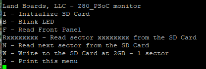
Z80_PSoC Monitor
- Press SW26 button (one in from upper left) button on Front Panel For 8 Bit Computers to run the Monitor
- PSoC Code Github repo
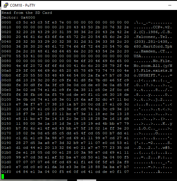
- Type to check the SD card
R4000
- Result:
Multiboot Multicomp (MULTIBOOT_CPM)
- CP/M Multiboot - Runs MultiComp 512KB SRAM version
- Insert "M/CPM 512KB" SD card
- Insert USB B cable
- Run PuTTY
- 115,200 baud
- Card will power up and cycle through all the LEDs on the Front Panel
- Press SW25 (upper left button) on Front Panel For 8 Bit Computers to run Multiboot software
- PuTTY will display
Press [SPACE] to activate console
- Press SPACE
- Press H for help menu
>
  Available Commands:

  :ccxxxxiibbbbbb       Load Intel-Hex file record
  Rxxxx         Run from address xxxx
  Sddd          System boot
  Iddd          Init: Format directory
  Pddd[,xxxx]   PutSys: write system image[,loadaddress]
                (No address: re-use last loadaddress)
  Gddd[,xxxx]   GetSys: load system track

  Dxxxx[,yyyy]  Dump memory from xxxx [,to yyyy]
                D (no address) shows next block
  Cxxxx         Change/show memory at xxxx
                CR advances "," quits

  ddd is a decimal volume number,
  xxxx, yyyy is a hexadecimal address.
  Leading zeros may be omitted.
  ESC or ^C aborts.
- Type Snnn to select OS at multiboot
- S1 - Dos+ 2.5 Copyright 1986 (c) by C.B. Falconer, CCP+ Ver. 2.2 (CP/M 2.2 compatible)
- S2 - CP/M 2.2 (c) 1979 by Digital Research
- S3 - CP/M Version 3.0 BIOS (2016/9/13)
- S4 - MP/M II V2.1
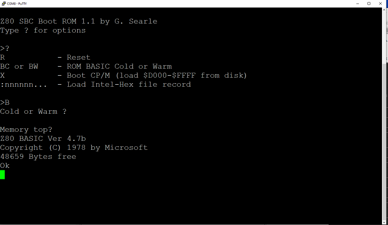
- S5 - Z80 BASIC Ver 4.7b, Copyright (C) 1978 by Microsoft
- S6 - ZSDOS v1.1 (c) 1986-8 Harold F. Bower & Cameron W. Cotrill, ZCPR2 (c) 1982 by Richard Conn (CP/M 2.2 compatible)
- S7 - ZCPR compatible system for CP/M+ (CP/M 3.0) by Simeon Cran
- SBC-2G-512 on Retrobrewing site - Original author
- GitHub copy of SBC-2G-512
Z80 BASIC Ver 4.7b
Reference Designs
Hackaday Page
Videos
